Audio Isolator Modules
4
Addendum, Canadian Applications PN 52196ADD:A 9/20/2003
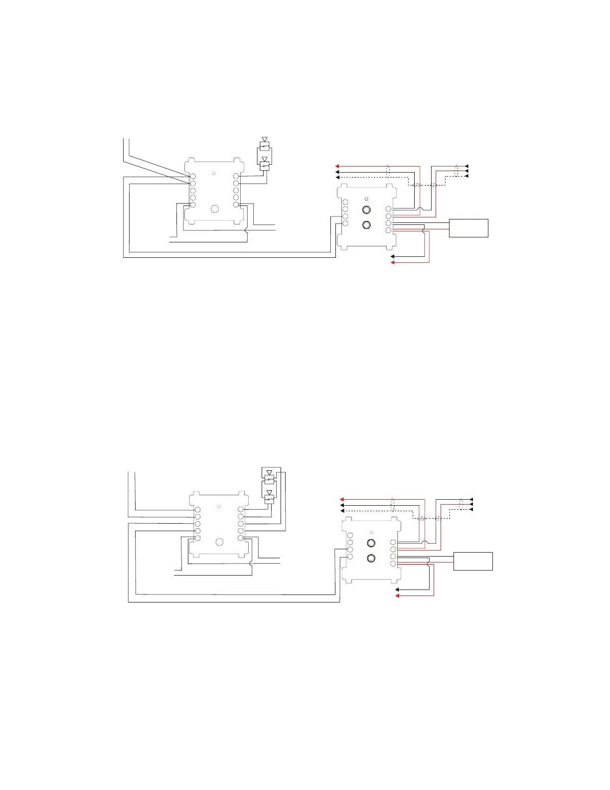
Figure 4 RSM-1/AIM-1 Speaker Circuit Connections, Unsupervised, Style Y (Class B)
Figure 5 RSM-1/AIM-1 Speaker Circuit Connections, Supervised, Style Z (Class A)
90
81
72
63
54
-
-
+
+
90
81
72
6
3
54
+
+
+
+
+
+
+
+
-
-
-
-
-
-
-
-
Voice-RSM-1-Yspkr.cdr
SLC to next device (Twisted-
pair wiring; see your control
panel manual to determine
whether shielding is
recommended.)
To next control module (last
device returns to amplifier
for supervision)
Audio Branch Circuit
SLC from control
panel or previous
device
(Twisted-pair wiring;
see your control
panel manual to
determine whether
shielding is
recommended.)
Speaker Circuit to
another device or end-
of-line resistor.
24VDC
power to
end-of-line
resistor or
next device
AA-100
AA-120
Signaling Devices
3.75W Max
RSM-1 or AIM-1
FCM-1
To switched
24VDC
power
24VDC to be applied only in alarm state.
RSM-1 only - the 24VDC power must be
interrupted for 2 seconds to override the
silence button. See the RSM-1 paragraph
under the heading "Description of Modules"
on page 2 of this addendum.
*
*
90
81
72
63
54
-
-
+
+
90
81
72
63
54
+
+
+
+
+
+
+
+
+
+
-
-
-
-
-
-
-
-
-
-
Voice-RSM-1-Zspkr.cdr
SLC to next device (Twisted-pair
wiring; see your control panel
manual to determine whether
shielding is recommended.)
To next control
module (last device
returns to amplifier
for supervision)
Audio Branch Circuit
SLC from control
panel or previous
device
(Twisted-pair wiring;
see your control
panel manual to
determine whether
shielding is
recommended.)
FCM-1
24VDC
power to
end-of-line
resistor or
next device
Speaker Circuit
to another
device or end-of-
line resistor.
AA-100
AA-120
Signaling Devices
3.75W Max
RSM-1 or AIM-1
To switched
24VDC
power
24VDC to be applied only in alarm state.
RSM-1 only - the 24VDC power must be
interrupted for 2 seconds to override the
silence button. See the RSM-1 paragraph
under the heading "Description of Modules"
on page 2 of this addendum.
*
*
www.PDF-Zoo.com
 Loading...


