EasyManua.ls Logo

Honeywell NTC20k - User Manual

Honeywell NTC20k
3 pages
Print Icon
To Next Page IconTo Next Page
Loading...
3WIA-0B2700-060
1
感謝您購買本公司的產品!為使產品能正常運作,請您詳閱使用手冊,並請依照說明操作。謝謝!
Thanks for choosing our product! Please read carefully and follow this instruction before using!
產品附件清 Product accessories list
1. 產品:壁掛式 Wall mount
附件:如下
傳訊器
數量:1
螺絲 Screws
數量:4
使用說明書 Manual
數量:1
產品中有害物質的名稱及含量
數量:1
2. 產品:外氣 Outside Air
附件:如下
傳訊器
數量:1
螺絲 Screws
數量:4
使用說明書 Manual
數量:1
產品中有害物質的名稱及含量
數量:1
安裝方式 Installations
1. 請選定安裝傳訊器的位
Please decide right position for installation.
2. 將底座以螺絲固定在欲安裝的牆面或裝線盒上
Fix the base with screws on the wall
1
請依接線圖連接訊號線 (電阻&電壓輸出,請參考接線圖一)
Please refer Figure 1 (Resistance & Voltage Output ).
2
PC (LED 面朝上),插入接線端子台,並將 PC 板崁入正確位置
Connect properly the PC board to the terminal ( LED is on top )
3. 安裝線材請採用隔離線(15AWG / 17AWG / 22AWG)
Please apply 15AWG / 17AWG / 22AWG cable for installation.
*注意:接線前後,請勿接上電源,以免造成機板損壞,或發生危險
Notice: Please remove power from unit before wiring input and output connection, in order to avoid any damage or hazard.
接線方式如Please refer to the wiring Figures as following
端子接線方式 Wiring figure
NTC20k/ Pt1000&電壓輸出 Voltage Output (RL> 2.5KΩ at 24V DC)
圖一
Figure 1
注意: 請勿接線或碰觸到 AC 110 ~ 220V 的電源
Notice: Do not connect to AC 110 ~ 220V power supply.
** NTC 20K 2-wire sensor 直接連接”AB 端子輸出;若 Pt1000 3-wire sensor 直接連接”ABb”端子即可。
NTC 20K 2-wire type directly connected to the "A, B" terminal output; if Pt1000 3-wire directly connected "A, B, b" terminal output.
溫溼度傳訊器(NTC20k/Pt1000 & 電壓輸出)使用說明書
Temperature / Humidity Transmitter (NTC20k/Pt1000 & Voltage Output) Manual
NTC20K And
Pt1000 Sensor
Question and Answer IconNeed help?

Do you have a question about the Honeywell NTC20k and is the answer not in the manual?

Overview

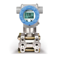
This document describes the Honeywell Temperature / Humidity Transmitter, available in NTC20k/Pt1000 and Voltage Output models. It serves as a user manual, providing instructions for installation, setup, operation, and maintenance.

Function Description

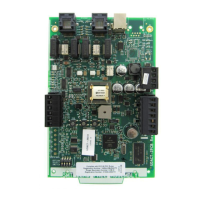
The Honeywell Temperature / Humidity Transmitter is designed to measure and transmit temperature and humidity data. It offers both NTC20k/Pt1000 sensor options for temperature measurement and a voltage output for data transmission. The device supports various temperature ranges and voltage output selections, making it adaptable to different application requirements. The user can configure these settings using jumpers on the device's PCB. The transmitter also features a user-friendly interface with LEDs for status indication and push-buttons for mode selection and value adjustment, facilitating calibration and reset operations.

Important Technical Specifications

Product Models:

  • Wall Mount: Includes transmitter, 4 screws, and a manual.
  • Outside Air: Includes transmitter, 4 screws, and a manual.

Temperature Measurement:

  • Sensor Types: NTC20k and Pt1000.
  • Configurable Temperature Ranges (via jumpers JP1-JP5):
    • 0~50°C (Default)
    • 0~100°C
    • -50~50°C

Voltage Output:

  • Output Type: Voltage Output (RL > 2.5KΩ at 24V DC).
  • Configurable Voltage Output Ranges (via jumpers JP6-JP10):
    • 0~10V (Default)
    • 0~5V
    • 1~5V

Wiring:

  • Recommended Cable: 15AWG / 17AWG / 22AWG shielded cable.
  • Power Supply: Do not connect to AC 110~220V power supply.
  • Sensor Wiring:
    • NTC 20K (2-wire type) connects directly to "A, B" terminals.
    • Pt1000 (3-wire type) connects directly to "A, B, b" terminals.

User Interface:

  • LED Display: Indicates status and values during operation and adjustment.
  • Push-buttons (SW2, SW3, SW4): Used for mode selection, value adjustment (zero and span), and reset.

Usage Features

Installation:

  1. Position Selection: Choose an appropriate location for the transmitter.
  2. Mounting: Fix the device's base to the wall or junction box using screws.
  3. Wiring:
    • Connect signal wires (resistance & voltage output) according to the provided wiring diagram.
    • Insert the PC board (LED side up) into the terminal block and secure it correctly.
    • Ensure power is removed before wiring to prevent damage or hazards.

Configuration (Jumpers):

  • Temperature Range: Set by shorting or opening jumpers JP1-JP5.
  • Voltage Output Range: Set by shorting or opening jumpers JP6-JP10.

Operation Modes (via SW2, SW3, SW4):

  1. Mode 0 (Normal Display): Shows normal operation. LEDs can be checked.
  2. Mode 1 (Humidity Calibration): Adjust humidity in 0.1%RH increments. Press SW2 once to enter, then use SW3(+) and SW4(-) for adjustment. LED2 lights up.
  3. Mode 2 (Humidity Zero Adjustment): Adjust humidity 0V/1V zero. Press SW2 twice to enter, then use SW3(+) and SW4(-) for adjustment. LED1 and LED3 light up.
  4. Mode 3 (Humidity Span Adjustment): Adjust humidity 5V/10V span. Press SW2 three times to enter, then use SW3(+) and SW4(-) for adjustment. LED2 and LED3 light up.
  5. Mode 4 (Reset Mode): Reset all calibration values to zero ("YES") or retain current values ("NO"). Press SW2 four times to enter, then use SW3 or SW4 to select. LED1, LED2, and LED3 are all lit.
  6. Return to Mode 0: Press SW2 five times to return to normal display.

Entering Adjustment Modes:

  • Simultaneously press and hold SW3 and SW4 for approximately 2 seconds until LEDs start flashing.
  • Press SW2 to select the desired mode.
  • Use SW3 and SW4 to adjust values within the selected mode.
  • If no mode is selected after 10 LED flashes, the device automatically returns to Mode 0.
  • If no action is taken for 25-30 seconds after entering a mode, the device automatically returns to Mode 0.

Maintenance Features

Calibration and Adjustment:

  • The device allows for precise calibration of humidity (zero and span) using the SW2, SW3, and SW4 buttons in dedicated operation modes. This ensures accuracy over time.

Reset Functionality:

  • A "Reset" mode (Mode 4) is available to either reset all calibration values to their factory defaults (zero) or to retain existing settings. This is useful for troubleshooting or re-commissioning the device.

Troubleshooting Guidance:

  • The manual emphasizes the importance of removing power before wiring to prevent damage, indicating a safety-conscious design and a clear instruction for maintenance personnel.
  • The LED indicators provide visual feedback on the device's status and current mode, aiding in diagnostics and ensuring correct operation during setup and adjustment.

Honeywell NTC20k Specifications

General IconGeneral
BrandHoneywell
ModelNTC20k
CategoryTransmitter
LanguageEnglish

Related product manuals