14 PRO-2200 Intelligent Controller PRO22ICInstallation Guide
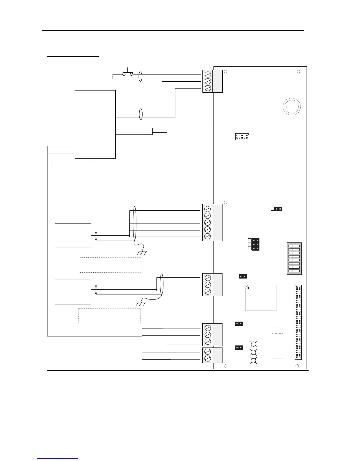
Wiring Diagram
CONTROLLER
BOARD
485-Com +
485-Com -
Com-Gnd
RS 485
Com
Bus Cable To
Other Panel
Power
RS-485
Termination
ABC
1
2
3
1
2
3
1
2
3
1
2
3
4
5
1
2
S1
Configuration
Dip Switches
J3
No Charging - C
No Charging - N/C
+12VDC Power
Supply
+
DC Output
-
J2
NC
PWR +
PWR -
Connect to chassis GND
at one side ONLY!
485-Com +
485-Com -
Com-Gnd
J9
J12
J13
LAN Card
Connector
Memory Expansion Connector
J14
J4
J5
J6
123
Note
Com-RTS
Com-CTS
Com-Gnd
RS 485 or
RS 232 Com
Bus Cable
485-Com +, or, Com-TXD
485-Com -, or, Com-RXD
NC
Tamper
Power Fail
Tamper Switch
(In Close Position
when Cabinet Door
Is Closed)
Switch Common
Low Battery - C
Low Battery - N/C
Input ? Common
Input ?
Any Supervised
Input On Any
Adjacent Rack
Mounted Board
(OPTIONAL)
CardRack PWR & Com Harness
Note
PWR +
PWR -
Do NOT tie PWR- to chassis GND !
Port 2
Port 1
Port 3
Connect to chassis GND
at one side ONLY!
88
7
6
58
4
3
2
1
Battery
Lithium 3V
PROM
U1
U1 1
Note: For N-485 Communication Connections, twist the blue pair together and use as the
common; use the orange pair as your data pair, observing polarity. Connect the
external drain shield to the appropriate earth ground on one end.
 Loading...