22 www.honeywell.com
Installing the PRO4200 Two Reader Module
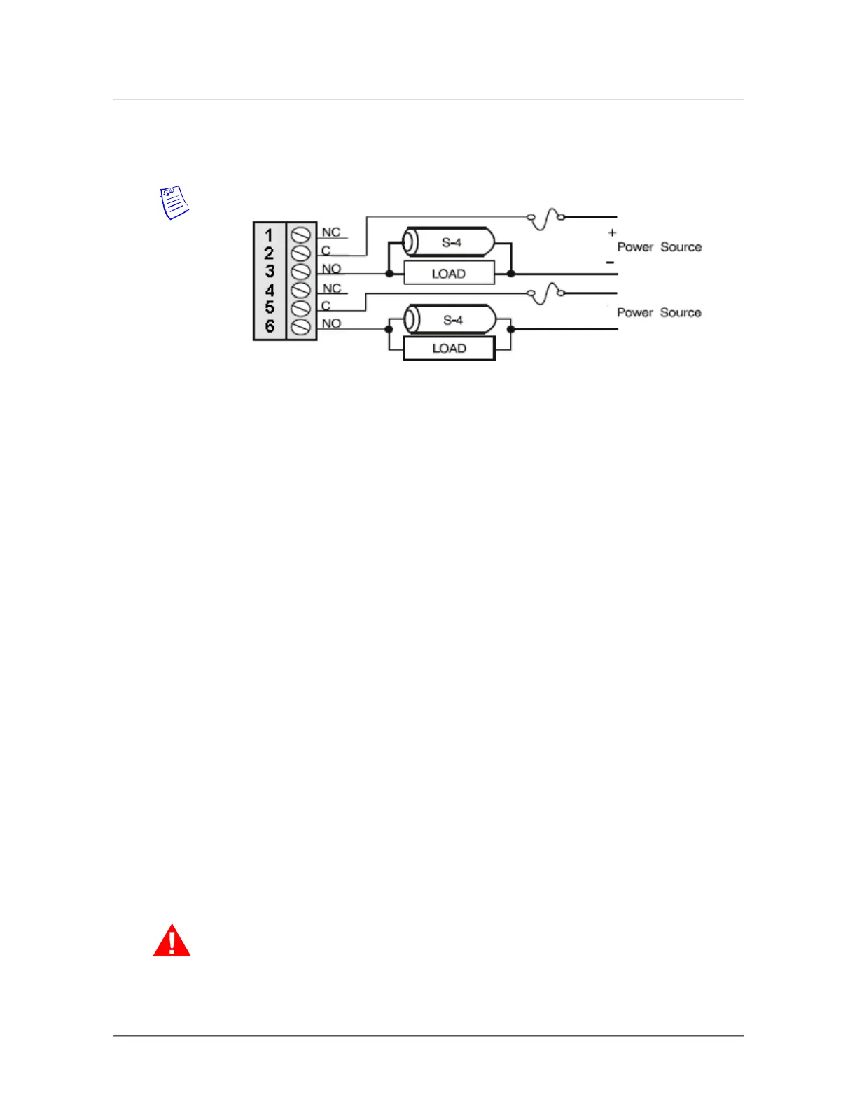
Wiring Diagram for Connectors 7 through 10
mounted in its own enclosure creating the need to monitor cabinet tamper and power
fault detection inputs. The two additional general-purpose inputs and outputs provided
allow for the monitoring of extra sensors and control of local horns or other
equipment.
Installing the Module
1. Set Jumpers and DIP switches.
2. Mount this board in the appropriate enclosure - If this board is being mounted
in a rack, the component side of the board is to your right as you face the rack.
3. Connect the communications and power supply to the circuit boards with the
Power Supply Harness.
Warning: DO NOT CONNECT THE POWER SUPPLY TO THE AC SOCKET
UNTIL ALL WIRING HAS BEEN INSTALLED AND RECHECKED.
4. Connect wiring to the reader interfaces as appropriate.
5. Connect wiring to input sensors or install jumper wire as appropriate.
6. Connect relay output wiring as appropriate.
7. Connect communications wiring to the Intelligent Controller.
8. Recheck wiring for correct connections and continuity.
9. When all boards have been installed, connect the power supply cord for proper
10.connections and power.
11. Set up the panel controls using the host software.
 Loading...