Installing the PRO4200 Two Reader Module
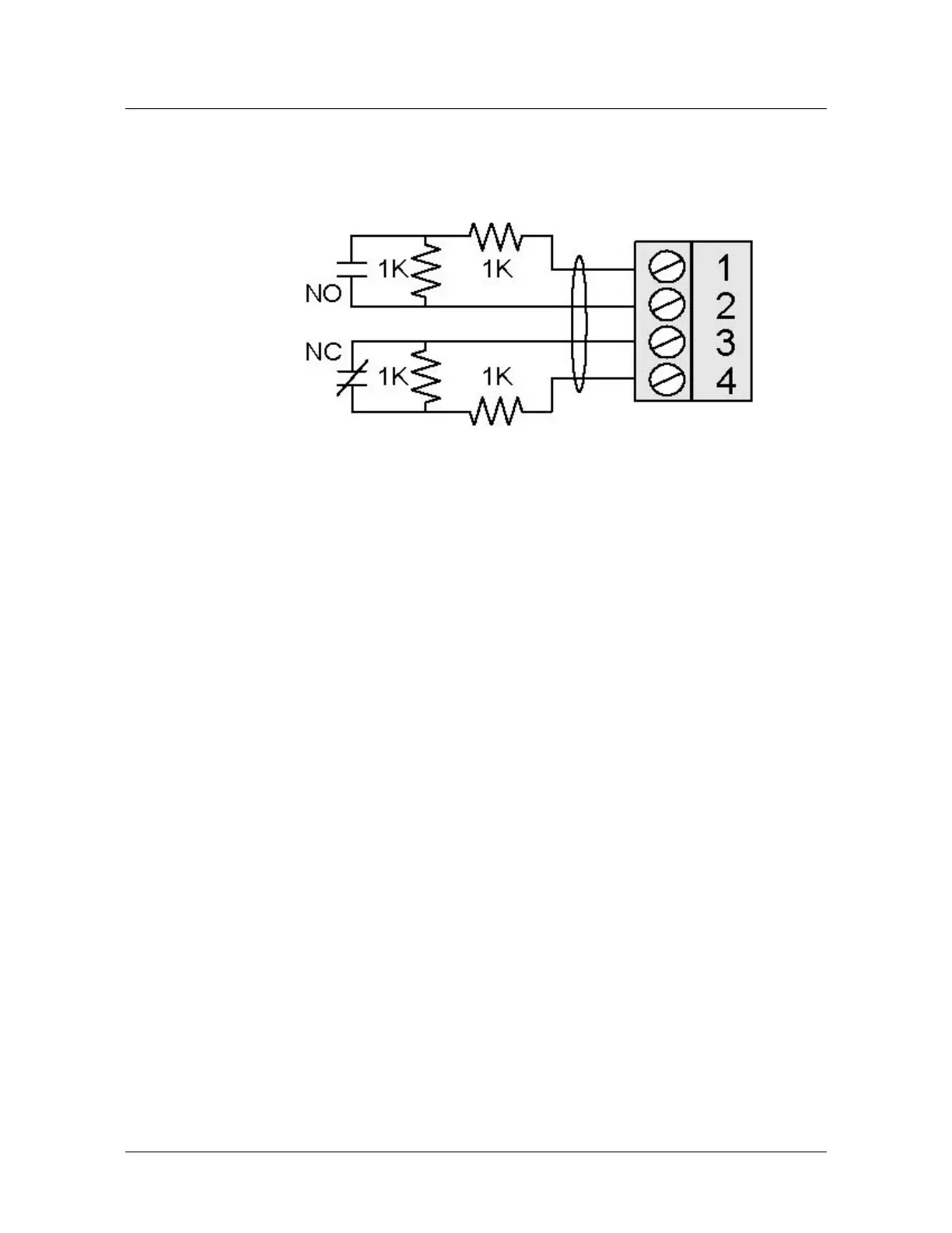
Wiring Diagram for Connectors 7 through 10
PRO4200 Two-reader module User Guide, Document 800-25698V1 21
Control Output Wiring
Six form-C relay contacts are provided for controlling door strike or other devices.
Each may be assigned to door-related functions or general-purpose output. They are
configurable as standard (energize to activate) or fail-safe (de-energize to activate) via
host software.
The energized or ON time of each relay can be configured using Pulse control for
single or repeating pulses via host software. The energized or ON time for a single
pulse can be extended up to 24 hours. For repeating pulses, the on/off time can be
defined in 0.1 second increments and be repeated up to 255 times.
Relays 0 and 2 are rated for and normally used to control the door locks associated
with readers 0 and 1 respectively. While Relays 0 and 2 are sized to handle the typical
loads generated by electrical locks, load switching can cause abnormal contact wear
and premature contact failure. Switching of inductive loads (i.e., strike) also causes
EMI (electromagnetic interference) which may interfere with normal operation of
other equipment. To minimize premature contact failure and to increase system
reliability, a contact protection circuit is highly recommended. The following two
circuits are suggested. Locate the protection circuit as close to the load as possible
(within 12 inches [30cm]); the effectiveness of the circuit decreases as the distance
from the load increases.
Note: Only relays 0 and 2 can be used for door hardware in a UL installation
Relays 1 and 3 are dry-circuit level signal relays typically used to indicate the status of
the door lock. Relays 4 and 5 are general-purpose relay outputs and are not available
when the board is rack-mounted.
Use sufficiently large gauge of wires for the load current to avoid voltage loss.
Mounting Options
This board can be mounted on-edge in the rack-mount enclosure provided by
Honeywell or it can be mounted flat against any surface using standoffs under the
mounting holes provided in each of the four corners of this board.
When this board is rack-mounted, the connectors for two general-purpose inputs, two
general-purpose outputs, and two dedicated inputs are not accessible and should not
be used.
The most common reason for mounting a board flat is that it is being installed
remotely to be located near the door(s) being monitored. In this case it will be
 Loading...