20 www.honeywell.com
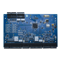
Installing the PRO4200 Two Reader Module
Wiring Diagram for Connectors 7 through 10
configuration is shown below. If Beeper Control is not used, its terminal can be
programmed to be the second wire for the two-wire bi-colored reader LED.
To fully utilize each reader port, a 6-conductor cable (18AWG) is required. Reader
port configuration is set via host software
Input Wiring
Inputs 0 to 7 may be configured to use normally open or normally closed contacts and
non-supervised or supervised (with standard ±1% tolerance 1K ohm). Four of these
inputs have default functional definitions, but all eight can be configured to monitor
general-purpose sensors.
By default, Input 0 is defined as the Door Status Input corresponding to reader 1 and
Input 1 is defined as the REX input corresponding to reader 1. Also by default, Input 2
is defined as the Door Status Input corresponding to reader 2 and Input 3 is defined as
the REX input corresponding to reader 2. Inputs 4, 5, 6 and 7 are general purpose
inputs that can be used to monitor sensors or as control inputs. Inputs 6 and 7 are not
accessible when the board is rack mounted.
Inputs TMP and PFL are typically used for monitoring cabinet tamper and power
failure respectively. These two inputs are not supervised and are not accessible when
the board is rack-mounted. These inputs were primarily provided for the case when
this board is mounted remotely and cannot take advantage of the tamper and power
fail detect inputs on the controller board. If these inputs are not used, install a short
piece of wire at the input to indicate safe condition.
Input configuration including debounce and hold time is set via host software.
Table 5:
LED Output-> High Tri- Stated Low
Single Color LED LED ON LED OFF LED OFF
Bi- Color LED Green LED ON Both LEDs OFF Red LED ON
 Loading...