Installing the PRO4200 Two Reader Module
Wiring Diagram for Connectors 7 through 10
PRO4200 Two-reader module User Guide, Document 800-25698V1 19
Note:
Reader, Input, and Output addresses on the PRO4200 panel are labeled starting
with address 0. This translates to address 1 in the WIN-PAK per the example below:
Note: The SIO board port for a PRO42IC in WIN-PAK is port 6 and is set as the
default.
Reader Wiring
The following Honeywell reader module numbers have been approved by UL for use
with the PRO4200: OM40BHONA, OM55BHONA, OP10HONE, OP30HONE,
OP40HONE, OP90HONE, OT30HONA, OT31HONA, OT35HONA, and
OT36HONA.
Each reader port supports a reader with TTL interface. Power to the reader is
selectable as 5VDC or 12VDC (pass-through). This selection is done by setting the
jumpers J2 for reader 1 and J3 for reader 1. Set jumper at position "5" for 5VDC or
"12" for pass-through 12VDC. The factory defaults set J2 and J3 to "5".
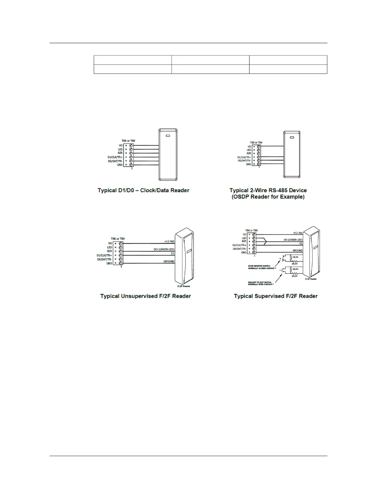
For wiring to a reader port
The LED control terminal in each reader port can be configured via host software to
support one-wire single or bi-colored reader LED. An example of the most common
PRO4200 Device PRO4200 Address WIN-PAK Address
Reader\ Input\ Output 0 1
Reader\ Input\ Output 1 2
Table 4: Settings for Wiring to a Reader Port
Terminal
Typical Wire
Color
Wiegand
Reader
Clock/Data
Readers
1 Red Power (5 or
12 Vdc)
Power (5 or 12
Vdc)
2 Brown LED control LED control
3 Yellow Beeper
Control
Beeper
Control
4 White Data 1
Signal
Clock Signal
5 Green Data 0
Signal
Data 0
Signal
6 Black Common Common
 Loading...