MU2C-0028SZ20 R1404
2
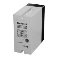
R4343D, R4343E
12
11
10
9
8
7
6
5
4
3
2
1
0,2A
L
N
9
8
7
6
5
4
3
2
1
R4343D (recommended)
Mains supply
voltage
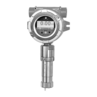
Rectification
type sensor
contacts
F (blue)*
G (yellow)*
*
only for C7012A/C/G
(C7
012 and R4343D supply voltages must match)
R4343E (recommended)
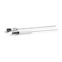
UV power tube
contacts
blue
yellow
TYPICAL WIRING DIAGRAMS
SPECIFICATIONS
MODELS:
ELECTRICAL RATING:
115Vac, 230Vac (+ 10 % to - 15%),
50/60 Hz.
CONTACT: 2 isolated DPDT contacts. Rating: 2A at 0.65
power factor.
AMBIENT TEMPERATURE LIMITS:
-10 to + 60 °C
MAXIMUM RELATIVE HUMIDITY:
90% RH at + 40 ° C.
DEGREE OF PROTECTION: IP40
FLAME FAILURE RESPONSE TIME *
Less than one second (standard models).
Other timings available on request.
CLASSIFICATION: OOOOXN
INSTALLATION
IMPORTANT
1. Disconnect the power supply before beginning the
installation.
2.Whenever possible, use the burner/boiler
manufacturer’s instructions. If these are not
provided, follow the instructions below.
ONLY FOR R4343E: you have an internal fuse to protect
your flame detector.
F 0.032 A 250 V/F
Mount the subbase
1. The subbase may be installed in any plane, but the
vertical is recommended.
2. Ensure that sufficient space is available to access the
relay for servicing or removal.
Wire the subbase
1. Wiring and overload protection should conform to local
electrical regulations
2. Verify that the wiring is correct before plugging in the
relay.
CHECKOUT AFTER INSTALLATION
Check the points on this list before starting the
system
• That system overload protection is correct.
• That wiring connections are correct and that all terminal
screws are tight
• That the flame detector is correctly installed and that
the correct flame detector is being used.
• That the burner is completely purged and ready to fire
with the fuel lines purged of air
• That the combustion chamber and flues are clear of
fuel. That power is on at the system main switch.
english
sepyTsetoN
trfF
*
egatloVylppuS
9001D3434R
rosnesepytnoitacifitcerroF
.ces1caV511
7101D3434R.ces1caV032
1401D3434R
For rectification type sensor,
Customer special
.ces2
caV032/511
)egatlovlaud(
-1401D3434R
500TS
rosnesepytnoitacifitcerroF.ces2
caV032/511
)egatlovlaud(
6001E3434R
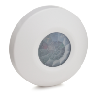
VUgnikcehcfles-nonroF
)repeeP-iniM(srosnes
.ces1caV511
4101E3434R.ces1caV032
8401E3434R
For non-self checking UV
sensors (Mini-Peeper),
Customer special
.ces2
caV032/511
)egatlovlaud(
-8401E3434R
500TS
VUgnikcehcfles-nonroF
)repeeP-iniM(srosnes
.ces2
caV032/511
)egatlovlaud(
Mount relay on the subbase
1. Plug the relay into the subbase.
2. Secure the relay to the subbase by tightening the two
captive screws on the relay face.
3. When installation is completed, check the flame current
value as described below.
Only for special models with dual supply voltage:
- apply 115Vac between T10 (L) and T11 (N)
- or apply 230vac between T12 (L) and T11 (N)
For all other models, apply supply voltage between T12 (L) and T11 (N)
12
11
10
0,2A
L
N
Mains supply
voltage
Only for special models with dual supply voltage:
- apply 115Vac between T10 (L) and T11 (N)
- or apply 230vac between T12 (L) and T11 (N)
For all other models, apply supply voltage between T12 (L) and T11 (N)
 Loading...