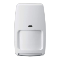
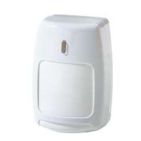
5800PIR-COM - Installation Instructions / Instructions de montage / Instrucciones de Instalación
PRELIMINARY DRAFT 8/25/09
14
12
13
3
1
2
7 - 9 ft*
(2.1 - 2.7m)
Satisfactory /
Satisfaisant /
Satisfactorio
No / Non / No
7'
2 m
20'
6 m
TOP
OPEN /
OUVERTURE / ABRIR
LOCATION / EMPLACEMENT / UBICACIÓN
1
2
MOUNT / MONTAGE / MONTAJE
5
ENROLL THE SENSOR, CONDUCT GO / NO GO
TEST, AND PERFORM WALK TEST /
ENRÔLEZ LE DÉTECTEUR, EXÉCUTEZ UN TEST
" TOUT OU RIEN " ET FAITES UN TEST PAR
DÉPLACEMENT /
REGISTRE EL SENSOR, REALICE UNA PRUEBA
PASA/NO PASA Y UN RECORRIDO DE PRUEBA
4
#6 x 1-1/4
(3.5 mm x 32 mm)
DETECTION PATTERNS / MODÈLE DE DÉTECTION / PATRONES DE DETECCIÓN
C
B
18-20
ACCESSORIES / ACCESSOIRES / ACCESORIOS
D
60' / 18m Wide Angle Lens / Objectif Grand-angle /
Lente Gran Angular [P/N 5-532-451-01 (Installed)]
Top View / Vue de Dessus / Vista Superior
Lens Masking / Masquage de L'Objectif / Enmascaramiento del Lente
Top View / Vue de Dessus / Vista Superior
Side View / Vue de Côté / Vista Lateral
Side View / Vue de Côté / Vista Lateral
100' / 30 m Long Range Curtain Lens /
Objectif Longue Portée /
Lente de Largo Alcance
[P/N 5-532-384-01 (Included)]
- Rear Tamper Breakaway Tab; MUST be
mounted
to a stud, solid wood, or with a robust wall anchor.
- Languette antisabotage arrière indiquant le
démontage de l'unité; DOIT être installée sur
un montant de cloison, une surface de bois solide
ou à l'aide d'un ancrage de gypse robuste.
- Lengüeta de seguridad trasera; DEBE montarse en un
travesaño, madera sólida o con un soporte para pared resistente.
LENS /
OBJECTIF /
LENTE
MASK / MASQUE / ENMASCARAMIENTO
1
2
CONNECT THE BATTERY /
METTRE LES PILES EN
PLACE / CONEXIÓN DE
LAS BATERIAS
3
Panasonic CR123A /
Duracell DL123A /
Honeywell 466
Tamper
See page 2 for more information /
Pour plus d'information, consultez
la page 2 /
Consulte la página 2 para obtener más
información
A
LENS CHANGE INSTRUCTIONS / INSTRUCTIONS DE REMPLACEMENT DE LAS LENTILLE/
INSTRUCCIONES DE CAMBIO DE LENTES
B
LOOK DOWN MIRROR REMOVAL AND STORAGE /
RETRAIT ET ENTREPOSAGE DU MIROIR À VUE
SOUS LE DÉTECTEUR / RETIRO Y
ALMACENAMIENTO DEL ESPEJO DE VISTA
ZONA 0
8
7
6
11
10
9
1
2
3
5
4
- To remove Look Down
Mirror, see B.
- Pour retirer le miroir à vue
sous le détecteur, consultez
la section B.
- Para retirar el Espejo
de vigilancia inferior,
consulte B.
33'
10 m
46'
14 m
60'
18 m
72'
22 m
85'
26 m
100'
30 m
3 m
3 m
10'
10'
0
0
7'
2 m
20'
6 m
33'
10 m
46'
14 m
60'
18 m
72'
22 m
85'
26 m
100'
30 m0
7'6"
2.3 m
0
7'
2 m
20'
6 m
27'
8 m
40'
12 m
53'
16 m
13'
4 m
33'
10 m
46'
14 m
60'
18 m
0
7'
2 m
20'
6 m
27'
8 m
43'
13 m
13'
4 m
33'
10 m
7'
2 m
20'
6 m
27'
8 m
43'
13 m
13'
4 m
33'
10 m
0
7'
2 m
20'
6 m
27'
8 m
40'
12 m
53'
16 m
13'
4 m
33'
10 m
46'
14 m
60'
18 m
0
7'6"
2.3 m
0
A
C
12-17
D
1-11
B
A
C
D
Look Down
Basses
Vista Zona 0
A
Lower
Courtes
Cercana
B
Long
Longues
Largo Alcance
D
Intermediate
Intermediaires
Intermedia
C
Select High Sensitivity / Loop 2 ONLY.
Sélectionnez Haute sensibilité / Boucle 2 SEULEMENT.
Seleccione SÓLO Alta sensibilidad/Bucle 2.
2
1
Observe correct polarity.
Veuillez observer la polarité.
Observe la polaridad correcta.
* 7 - 8.5 ft (2.1 - 2.6 m)
for Low Sensitivity. /
* 7 - 8.5 ft (2.1 - 2.6 m)
pour un niveau de sensibilité faible. /
* 7 - 8.5 ft (2.1 - 2.6 m)
para baja sensibilidad.
- Use only left OR right side
corner mounting holes.
- Utilisez uniquement les trous
de montage qui se trouvent
dans le coin gauche OU droit.
- Utilice agujeros de montaje,
únicamente derechos o
izquierdos.
SMB-10*
1
(P/N 0-000-110-01)
Swivel Mount Bracket
Support de montage pivotant
Soporte Giratorio
SMB-10C*
1
(P/N 0-000-111-01)
Swivel Mount Ceiling Bracket
Support pivotant pour montage au plafond
Soporte Giratorio de Cielo
IS2500-HSLK
1
35’ x 40’
(11 m x 12 m)
High Security Lens Kit
Kit d’objectif haute sécurité
Kit de lentes de alta seguridad
IS2500-PALK
2
35’ x 40’
(11 m x 12 m)
Pet Alley Lens Kit
Kit d’objectif avec couloir pour
animaux familiers
Kit de lentes inmunes a las mascotas
(Pet Alley)
* Not evaluated by UL.
Mounting Height:
Hauteur de montage:
Altura de la instalación:
1
7 – 9 ft (2.1 m – 2.7 m)
2
4 ft (1.2 m)
SPECIFICATIONS SPÉCIFICATIONS ESPICIFICACIONES
Power: Battery* (included). Alimentation : Pile* (incluse). Alimentación: Batería* (incluida). 1 x 3 V , Lithium / Litio; Panasonic CR123A /
Duracell DL 123A / Honeywell 466
Battery Life, years (typical): Durée de vie de la pile, en années (typique) : Duración de las baterías, años (típica): 4
RF Frequency: Fréquence radio : Frecuencia de RF: 345 MHz
Operating Temperature:
(for indoor use environment)
Température de fonctionnement : Temperatura de funcionamiento:
(para uso bajo techo)
-4° to 131° F (-20° to 55° C)
Relative Humidity, no
condensation:
Humidité relative, pas de condensation : Humedad relativa, sin condensación: 95% max.
Detectable Walk Rate: Vitesse de marche détectable : Velocidad de recorrido detectable: 0.7 – 7ft/Sec. (0.2 – 2.0m/Sec.)
Temperature Compensation: Compensations en Température : Compensación de Temperatura:
Advanced Dual Slope
A doble pente
Inclinación dual avanzada
* Battery Caution: Risk of fire,
explosion and burns. Do not
recharge, disassemble, heat
above 212° F (100° C), or
incinerate. Dispose of used
batteries promptly. Keep away
from children.
* Attention de batterie : Risque
d'incendie, d'explosion et de
brûlures. Ne rechargez pas,
démonter, chauffer au-dessus
de 212° F (100° C), ou
incinérer. Débarrassez-vous