WHEN INSTALLING THIS PRODUCT . . .
1. Read these instructions carefully. Failure to
follow them could damage the product or cause a
hazardous condition.
2. Check the ratings given in the instructions and on
the product to make sure the product is suitable for your
application.
3. Installer must be a trained, experienced service
technician.
4. After installation is complete, check out product
operation as provided in these instructions.
I
Disconnect power supply before wiring to prevent
electrical shock or equipment damage.
I
All wiring must comply with applicable codes and
ordinances. Be sure the power supply voltage agrees with
the rating on the relay label.
Fig. 3 shows a typical installation within a compart-
ment enclosure on the end of a baseboard heater. The
back of the compartment enclosure should be equipped
with embossing to clear mounting screws.
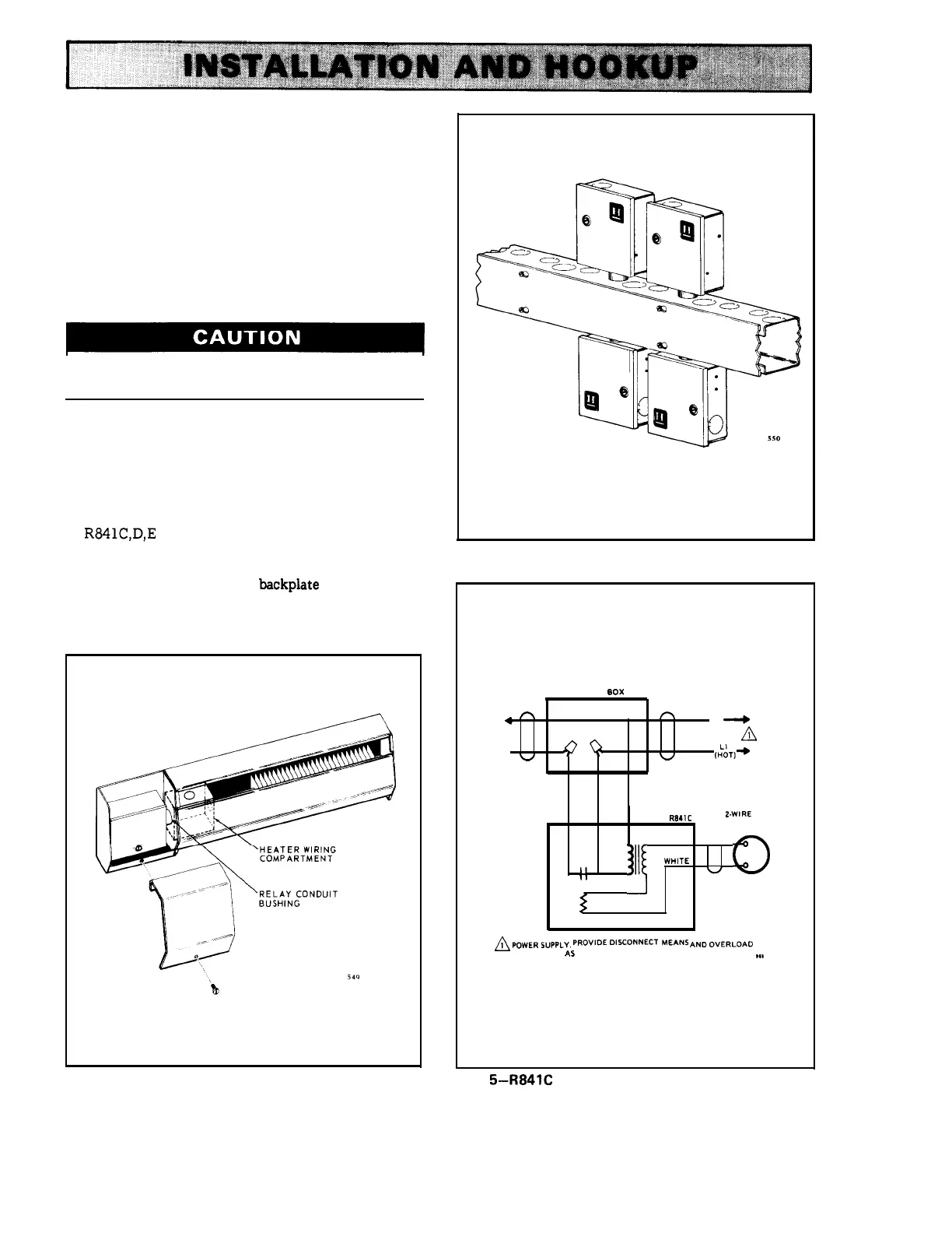
R841C,D,E
also may be mounted on a wireway
(Fig. 4) or junction box.
1. Fasten relay securely to mounting surface using
the 2 mounting holes in the
backplate or the conduit
bushing.
2. Disconnect the power supply.
FIG. 4–FOUR RELAYS MOUNTED ON WIREWAY.
JUNCTION
BOX
n
4
n
n
L2
~
A
4
f?Q
(;:T]~
w
w
RED BLACK BLUE
R841C
2.WIRE
LOW VOLTAGE
THERMOSTAT
RED
n
111~
WHITE
(~
II
u
II
RESISTANCE
HEATER
~
PIYUER5”PPLY. PRovlDEDl,coNNEcT
ME&N,
ANDovERLoAo
PROTECTION
AS
REQUIRED.
,.,
!
FIG. 3–TYPICAL INSTALLATION ON BASEBOARD
FIG.
5–R841C INTERNAL SCHEMATIC AND CON-
HEATER.
NECTION DIAGRAM FOR ONE RELAY.