Do you have a question about the Honeywell RIO and is the answer not in the manual?
Before assembly, verify all parts are present using lists and do not proceed if any item is missing or damaged.
Essential tools for assembly include electrical tape, Phillips screwdriver, pliers, safety glasses, step ladder, and wire strippers.
Optional tools that may assist assembly include an AC tester light, tape measure, wiring handbook, and wire cutters.
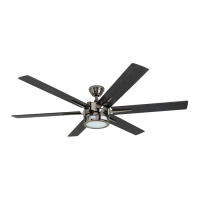
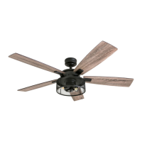
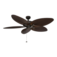
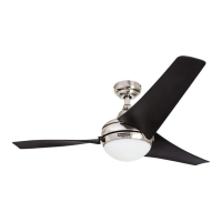
The net weight of the ceiling fan is 15.7 lbs. (7.12 kg).
Includes DANGER, WARNING, and CAUTION notices regarding power, installation, blade handling, and grounding for safe operation.
Turn off circuit breakers and wall switch before installation to prevent serious injury or death.
Details suitability of downrod, angle, and closemount styles for different ceiling heights and types.
Ensure blades are 30 inches from obstructions and at least 7 feet above the floor for safe operation.
Using correct hardware for the mounting bracket is crucial as it supports the entire fan assembly.
For angle mounting, ensure the open end of the mounting bracket faces the ceiling's peak for proper installation.
Partially loosen the two set screws in the yoke at the top of the motor housing before proceeding.
Remove the downrod pin and downrod clip from the downrod to prepare for installation.
Thread motor housing wires through the yoke cover, canopy, and out the top of the downrod.
Slide the downrod into the yoke, align holes, reinstall pin/clip, and retighten set screws.
Manage lead wires by measuring 8 inches and cutting excess wire if necessary.
If wires were cut, strip 1/2 inch of insulation from each wire end and twist strands.
Install the downrod ball into the mounting bracket, aligning the slot with the tab.
Insert the receiver into the mounting bracket with its flat side facing the ceiling.
Remove the canopy cover from the bottom of the canopy.
Align canopy with motor housing screw holes and secure with three closemount screws.
Raise the fan and place the canopy on the mounting bracket hook for wiring.
Ensure proper grounding and heed warnings about differing house wire colors; consult an electrician if needed.
Connect supply, receiver, and fan wires according to the diagram, matching colors and functions.
Identifies black (fan power), blue (light power), white (common/neutral), and green (ground) wires.
Lift canopy, align with mounting bracket slots, rotate, and install remaining screws and washers.
Insert blades into motor housing, align holes, and attach with blade screws and washers.
Connect light kit wiring, install bulbs, and secure the glass shade clockwise.
Allow bulbs and kit to cool before touching. Handle mercury-containing bulbs according to EPA guidelines.
Use the reverse switch for seasonal performance; wait for fan to stop before changing direction.
Set switch left for downward airflow (cooling) and right for upward airflow (heating).
Adjust thermostat and turn off fan when room is unoccupied to maximize energy savings.
The D/CFL switch in the battery compartment selects dimmer or CFL mode for bulbs.
The dimmer function works with incandescent bulbs only; it is not compatible with CFL bulbs.
Turn lights on/off with a press, or dim/brighten with a press-and-hold (incandescent bulbs only).
Press and hold power button for five seconds to activate a one-minute light delay shut-off.
Check power, connections, light kit fitter, motor restart, and ensure blades are not overweight.
Tighten blade and motor screws, or replace any cracked blades.
Tighten screws, balance blades, verify mounting bracket security and flushness against outlet box.
Re-install bulbs, check light kit connections, and verify wattage does not exceed limits.
Replace the remote battery or re-sync the remote to the fan by pressing specific buttons simultaneously.