RLV310 69-1854 6/27/05 1/2
This thermostat can be used to control a electric heating system such
as an baseboard heater, a radiant ceiling, a radiant floor, a convector,
etc. See minimum and maximum load requirement in section 5.
The thermostat cannot be used with the following:
• a resistive load under 2 A
• systems driven by a contactor or a relay (inductive load)
• fan-equipped heating systems
• central heating systems
SUPPLIED PARTS
• One (1) thermostat
• Two (2) 6-32 mounting screws
• Two (2) solderless connectors
TURN OFF POWER OF THE HEATING SYSTEM AT THE MAIN
POWER PANEL TO AVOID ELECTRIC SHOCK.
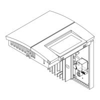
Loosen the screw holding the control module to the base. The screw
cannot be completely removed. Lift the control module to remove it
from the base.
Make the appropriate connections. Please note that the thermostat
wires are non-polarized; either wire can be connected to either termi-
nal.
NOTE: All cables and connections must conform to the local electri-
cal code. Special CO/ALR solderless connectors must be used when
connecting with aluminium conductors.
Align and affix the base to the
electrical box.
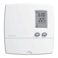
Set the switch at the back of the remov-
able part of the thermostat to °C or °F.
Replace the front part of the thermostat
on the base and secure it in place with
the screw.
Keep air vents of thermostat clean and
free from obstructions.
n
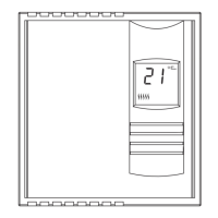
Description
1.
o
Installation
2.
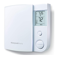
Temperature
display
Heating power
indicator
Temperature
adjustment
buttons
2-wire installation
4-wire installation
RLV310
User Guide
Electronic Thermostat