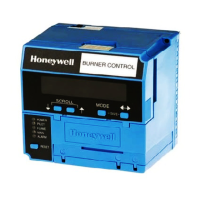
RM7800L1087; RM7840G1022,L1075; EC7840L1014 RELAY MODULES WITH VALVE PROVING
29 66-1162—2
APPENDIX B: RM7800L/40G,L, EC7840L IGNITION OPTIONS
Column 1 lists the ignition option.
Column 2 lists the figure letter that shows the connections for that option. The figure letters refer to the figures on pages 30–32.
Column 3 refers to the fuel changeover switch and how many connections or poles that would be required.
Table 17. RM7800L/40G,L, EC7840L Ignition Options
Ignition Options Figure Letter Fuel Changeover Poles
No Valve Proving
Single Fuel
- MFEP 10s A -
- MFEP 15s B -
- DSI C -
Dual Fuel
MFEP timed for both
- Gas 10s, Oil 10s D 2
- Gas 10s, Oil 15s E 2
- Gas 15s, Oil 10s F 2
- Gas 15s, Oil 15s G 2
- Gas 10s, Oil DSI H 3
- Gas 15s, Oil DSI I 3
- Gas DSI, Oil 10s J 3
- Gas DSI, Oil 15s K 3
- DSI both L 2
Valve Proving on Gas
Single Fuel
- MFEP 10s M -
- MFEP 15s Not Possible
- DSI N -
Dual Fuel
MFEP timed for both
- Gas 10s, Oil 10s O 4
- Gas 10s, Oil 15s P 4
- Gas 15s
, Oil 10s Not Possible
- Gas 15s
, Oil 15s Not Possible
- Gas 10s, Oil DSI Q 5
- Gas 15s
, Oil DSI Not Possible
- Gas DSI, Oil 10s R 4
- Gas DSI, Oil 15s S 4
- DSI Both T 4
Gas Direct Spark Ignition during VPS Selection (powering terminal 17) automatically
chooses 4 second Ignition Trial Period, regardless of configuration resistor JR1 status
CAUTION! The above options are ONLY suggestions—BE SURE to check local
approval agencies for timings acceptable for your application.

 Loading...


