7800 SERIES RELAY MODULES
32-00213—01 6
a
See Table 2.
b
2000VA maximum connected load.
c
See Tables 4 and 5.
Final Wiring Check
1. Check the power supply circuit. The voltage and fre-
quency tolerance must match those of the
RM7838A. A separate power supply circuit can be
required for the RM7838A. Add the required discon-
nect means and overload protection.
2. Check all wiring circuits and complete Static Check-
out in Table 7 before installing the RM7838A on the
subbase.
3. Install all electrical connectors.
4. Restore panel power.
STATIC CHECKOUT
After checking all wiring, perform this checkout before
installing the RM7838A on the subbase. These tests verify
that the Q7800 Wiring Subbase is wired correctly and that
the external controllers, limits, interlocks, actuators,
valves, transformers, motors and other devices are
operating properly.
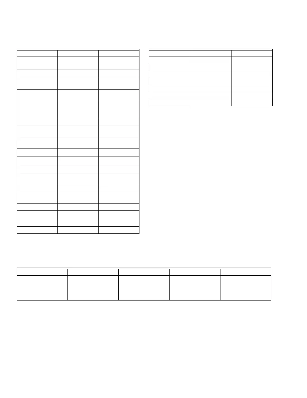
Table 3. Terminal Ratings
Terminal No. Description Ratings
GFlame Sensor
Ground
a
-
Earth G
Earth Ground
1
-
L2(N) Line Voltage
Common
-
3 Alarm 120 Vac, 1A pilot
duty.
4 Line Voltage
Supply (L1)
120 Vac, (+10/-
15%), 50/60- Hz
(±10%)
b
5Unused-
6 Start/Stop Switch
Input
120 Vac, 1 mA.
7 Running Interlock 120 Vac, 8A run,
43A inrush.
8 Intermittent Pilot
120 Vac.
c
9Main Fuel Valve
120 Vac.
c
10 Ignition
120 Vac.
c
F(11) Flame Sensor 60 to 220 Vac,
current limited.
12-18 Unused. -
19 High Fire Switch
Input
120 Vac, 1 mA.
20 Unused -
21 Run
Enable/Flame
Proven
120 Vac, 2A pilot
duty.
22 Shutter 120 Vac, 0.5A.
Table 4. Combinations for Terminals 8, 9 and 10.
Pilot Fuel 8 Main 9 Ignition 10
CFNo Load
BFNo Load
FFA
FNo LoadA
DF A
DDA
DNo LoadA
Table 5. Composition of each Combination.
ABCDF
4.5A ignition 50 VA Pilot Duty plus
4.5A ignition.
180 VA Ignition plus
Motor valves with:
660 VA inrush,
360 VA open,
250 VA hold.
2A Pilot Duty 65 VA Pilot Duty plus
Motor valves with:
3850 VA inrush,
700 VA open,
250 VA hold.
 Loading...