RM7840E,G,L,M
WIRING
5. Recommended grounding practices:
a. Use the earth ground to provide a connection
between the subbase and the control panel or the
equipment. The earth ground wire must be ca-
pable of conducting the current to blow the
20A fuse (or breaker) in event of an internal
short circuit. The RM7840 needs a low imped-
ance ground connection to the equipment frame
which, in turn, needs a low impedance connec-
tion to earth ground. For a ground path to be low
impedance at RF frequencies, the connection
must be made with minimum length conductors
that have a maximum surface area. Wide straps
or brackets are preferred rather than leadwires.
Be careful to ensure that mechanically tightened
joints along the ground path, such as pipe or
conduit threads or surfaces held together with
fasteners, are free of nonconductive coatings and
are protected against mating surface corrosion.
b. Each RM7840 has an earth ground terminal that
must be grounded to the metal control panel with
wire as short as practical. Each ground wire must
be capable of carrying a fault current equal to the
rating of the protective fuse (20A). A number 14
copper conductor is adequate but wide straps or
brackets are preferred rather than leadwires.
6. Recommended wire routing:
a. Flame detector leadwires:
12
M1977A
G
L
2
3
4
5
6
7
8
9
1
0
F
(L1
)
1
3
1
4
1
5
1
6
1
7
1
8
1
9
2
0
2
1
2
2
1
2
LOCKOUT INTERLOCKS
(INC. AIR FLOW SWITCH)
MASTER
SWITCH
LOW FIRE
START SWITCH
HIGH FIRE
PURGE SWITCH
5 SECOND IGNITION
(EARLY SPARK
TERMINATION)
MAIN FUEL
VALVE(S)
BURNER
CONTROLLER/LIMITS
BURNER MOTOR
(BLOWER)
HIGH FIRE
COMMON
LOW FIRE
MODULATE
120V ALARM
10 SEC. INTERRUPTED
PILOT/IGNITION
PREIGNITION
INTERLOCK
SERIES 90
FIRING RATE
MOTOR
SERIES 90
CONTROLLER
RECTIFYING FLAME
ROD, RECTIFYING
PHOTOCELL, OR INFRA-
RED (LEAD SULFIDE)
FLAME DETECTOR
C7027A, C7035A, OR
C7044A ULTRAVIOLET
FLAME DETECTOR
C7012A,C,E,F OR
C7076A,D ULTRAVIOLET
FLAME DETECTOR
120V, 60 Hz POWER SUPPLY. PROVIDE DISCONNECT MEANS AND OVERLOAD PROTECTION AS REQUIRED.
DO NOT WIRE TO ANY UNUSED TERMINALS.
FOR DIRECT SPARK IGNITION (OIL
OR GAS)
IGNITION
TRANSFORMER
MAIN VALVE
R
W
B
R
W
B
L1
(HOT)
L2
1
OR
OR
BLUE
BLUE
WHITE
YELLOW
L2
WHITE
WHITE
BLACK
BLACK
L1
L2
8
9
1
0
L
2
1
Q7800
15 SECOND
INTERRUPTED
PILOT VALVE
2
2
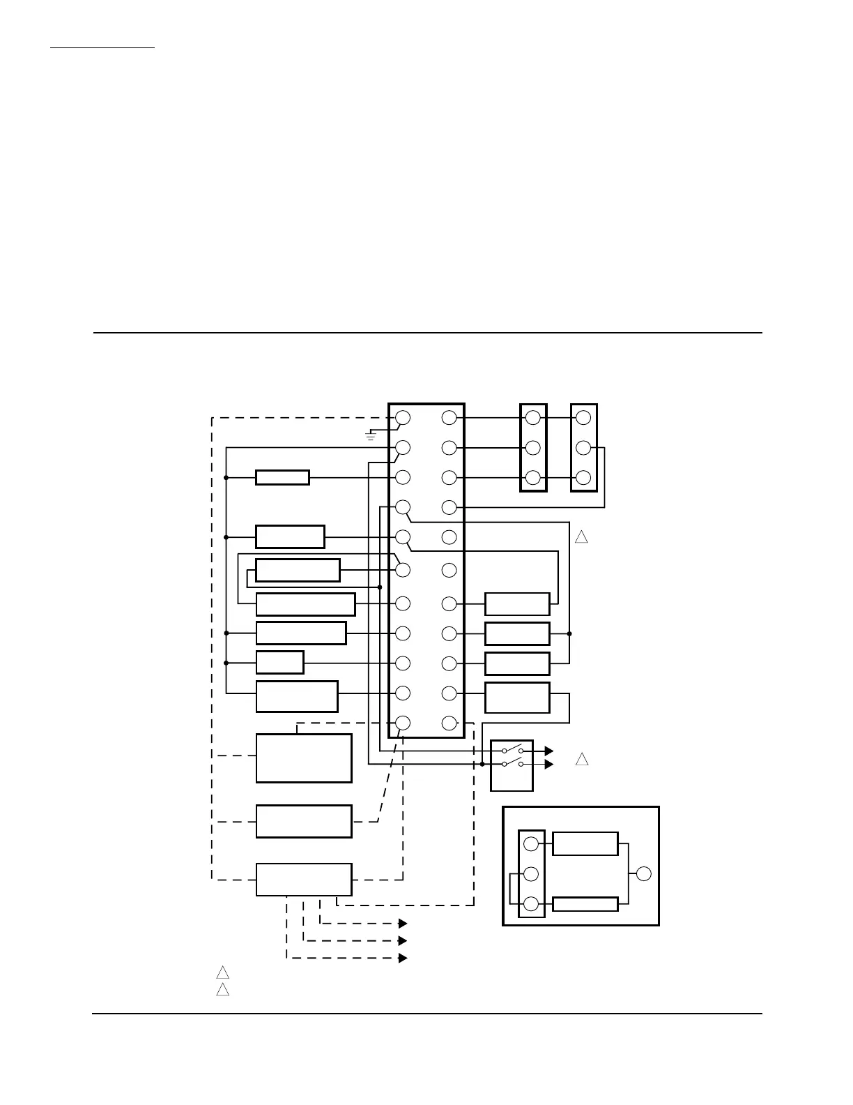
Fig. 7—Wiring RM7840E.
 Loading...

