RM7840E,G,L,M
WIRING
13 65-0087—2
1. Do not run high voltage ignition transformer
wires in the same conduit with the flame detec-
tion wiring.
2. Do not route scanner wires in conduit with line
voltage circuits.
3. Enclose scanner wires without armor cable in
metal cable or conduit.
4. Follow directions given in the flame detector
Instructions.
7. Maximum wire lengths:
a. For RM7840, the maximum length of leadwire is
300 feet to terminal inputs (Control, Preignition
Interlock, Running/Lockout Interlock, High Fire
Switch and Low Fire Switch).
M1978
G
L
2
3
4
5
6
7
8
9
1
0
F
(L1
)
1
3
1
4
1
5
1
6
1
7
1
8
1
9
2
0
2
1
2
2
1
2
RUNNING INTERLOCKS
(INC. AIR FLOW SWITCH)
MASTER
SWITCH
LOW FIRE
START SWITCH
5 SECOND IGNITION
(EARLY SPARK
TERMINATION)
MAIN FUEL
VALVE(S)
BURNER
CONTROLLER/LIMITS
BURNER MOTOR
(BLOWER)
HIGH FIRE
COMMON
LOW FIRE
MODULATE
120V ALARM
10 SEC. INTERRUPTED
PILOT/IGNITION
PREIGNITION
INTERLOCK
SERIES 90
FIRING RATE
MOTOR
SERIES 90
CONTROLLER
RECTIFYING FLAME
ROD, RECTIFYING
PHOTOCELL, OR INFRA-
RED (LEAD SULFIDE)
FLAME DETECTOR
C7027A, C7035A, OR
C7044A ULTRAVIOLET
FLAME DETECTOR
C7012A,C,E,F OR
C7076A,D ULTRAVIOLET
FLAME DETECTOR
120V, 60 Hz POWER SUPPLY. PROVIDE DISCONNECT MEANS AND OVERLOAD PROTECTION AS REQUIRED.
MAIN FLAME ESTABLISHING PERIOD (MFEP).
DO NOT WIRE TO ANY UNUSED TERMINALS.
FOR DIRECT SPARK IGNITION (OIL
OR GAS)
IGNITION
TRANSFORMER
2ND STAGE
FUEL VALVE
(OPTIONAL)
R
W
B
R
W
B
L1
(HOT)
L2
1
OR
OR
BLUE
BLUE
WHITE
YELLOW
L2
WHITE
WHITE
BLACK
BLACK
L1
L2
2
1
9
1
0
L
2
1
Q7800
JUMPER WIRE FOR 30s MFEP
2
15 OR 30 SEC.
INTERRUPTED/
INTERMITTENT
PILOT VALVE
1ST STAGE
FUEL VALVE
2
3
3
b. For flame detector leadwires, the maximum flame
sensor leadwire length is limited by the flame signal
strength.
8. Make sure loads do not exceed the terminal ratings.
Refer to the label on the RM7840 or to the ratings in
Specifications, see Table 1.
9. Check the power supply circuit. The voltage and
frequency tolerance must match those of the RM7840. A
separate power supply circuit may be required for the RM7840.
Add the required disconnect means and overload protection.
10. Check all wiring circuits and complete Static Check-
out, see Table 4, before installing the RM7840 on the
subbase.
11. Install all electrical connectors.
12. Restore power to the panel.
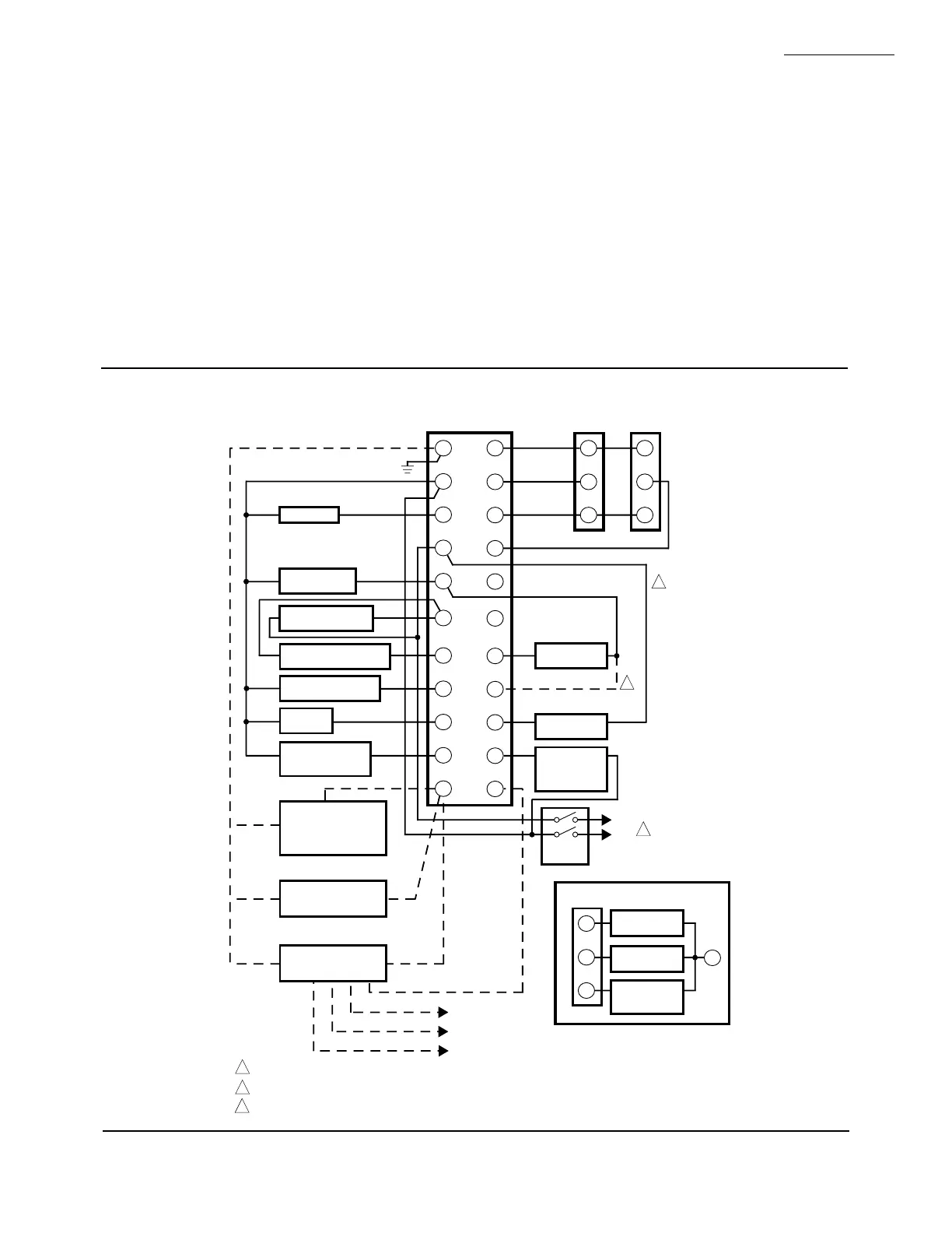
Fig. 8—Wiring RM7840G.
 Loading...

