RM7890, RM7895 100 Vac
Proper flame detector installation is the basis of a safe and
reliable flame safeguard installation. Refer to the instructions
packed with the flame detector and the equipment manufac-
turer instructions.
Keep the flame signal leadwires as short as possible from the
flame detector to the wiring subbase. Capacitance increas-
es with leadwire length, reducing the signal strength. The
maximum permissible leadwire length depends on the type
of flame detector, leadwire and conduit. The ultimate limiting
factor in the flame detector leadwire is the flame signal. See
Table 10.
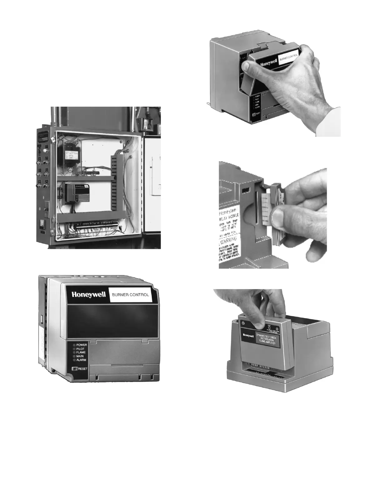
Fig. 8. Electrical panel installation.
Fig. 9. Wall or burner installation.
Fig. 10. Dust cover mounting.
Fig. 11. ST7800 Purge Card installation (RM7895 only).
Fig. 12. Flame signal amplifier mounting.
32-00216-01 14
 Loading...