RM7890, RM7895 100 Vac
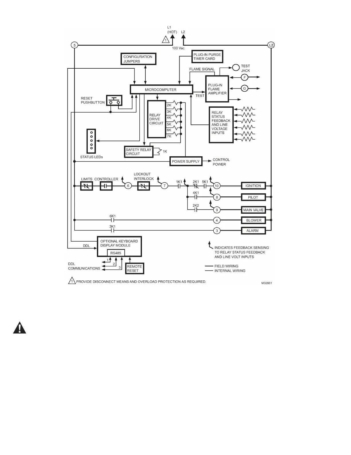
Fig. 5. Internal block diagram of the RM7895 Relay Module (see Fig. 7 for detailed wiring instructions).
WIRING
WARNING
Electrical Shock Hazard or Equipment and Control
Damage Hazard.
Can cause severe injury, death or equipment and
control damage.
Disconnect the power supply before beginning
installation.
1. For proper subbase wiring, refer to Fig. 6 and 7.
2. For proper remote wiring of the KDM, refer to the Specifi-
cations for the 2-line VFD KDM (65-0090), the 4-line LCD
KDM (32-00110), Network Data ControlBus™ Module
(65-0091) or Extension Cable Assembly (65-0131).
3. Disconnect the power supply from the main disconnect
before beginning installation to prevent electrical shock
and equipment damage. More than one disconnect may be
required.
4. All wiring must comply with all applicable electrical codes,
ordinances and regulations. Wiring, where required, must
comply with NEC, Class 1 (Line Voltage) wiring.
5. Recommended wire size and type: See Table 6 for the rec-
ommended wire sizes and part numbers.
32-00216-01 10
 Loading...