EasyManuals Logo
Home>Honeywell>Control Unit>RM7890

Honeywell RM7890 User Manual

Honeywell RM7890
28 pages
To Next Page IconTo Next Page
To Previous Page IconTo Previous Page
Page #9 background imageLoading...
Page #9 background image
RM7890, RM7895 100 Vac
3. For surface mounting, use the back of the subbase as a
template to mark the four screw locations. Drill the pilot
holes.
4. Securely mount the subbase using four no. 6 screws (not
provided).
NOTE: You might receive and error code 101 (via KDM) check
the screws securing the relay to the subbase to check
if they are not tight enough, re-tighten to insure there
is no gap between the relay and the subbase.
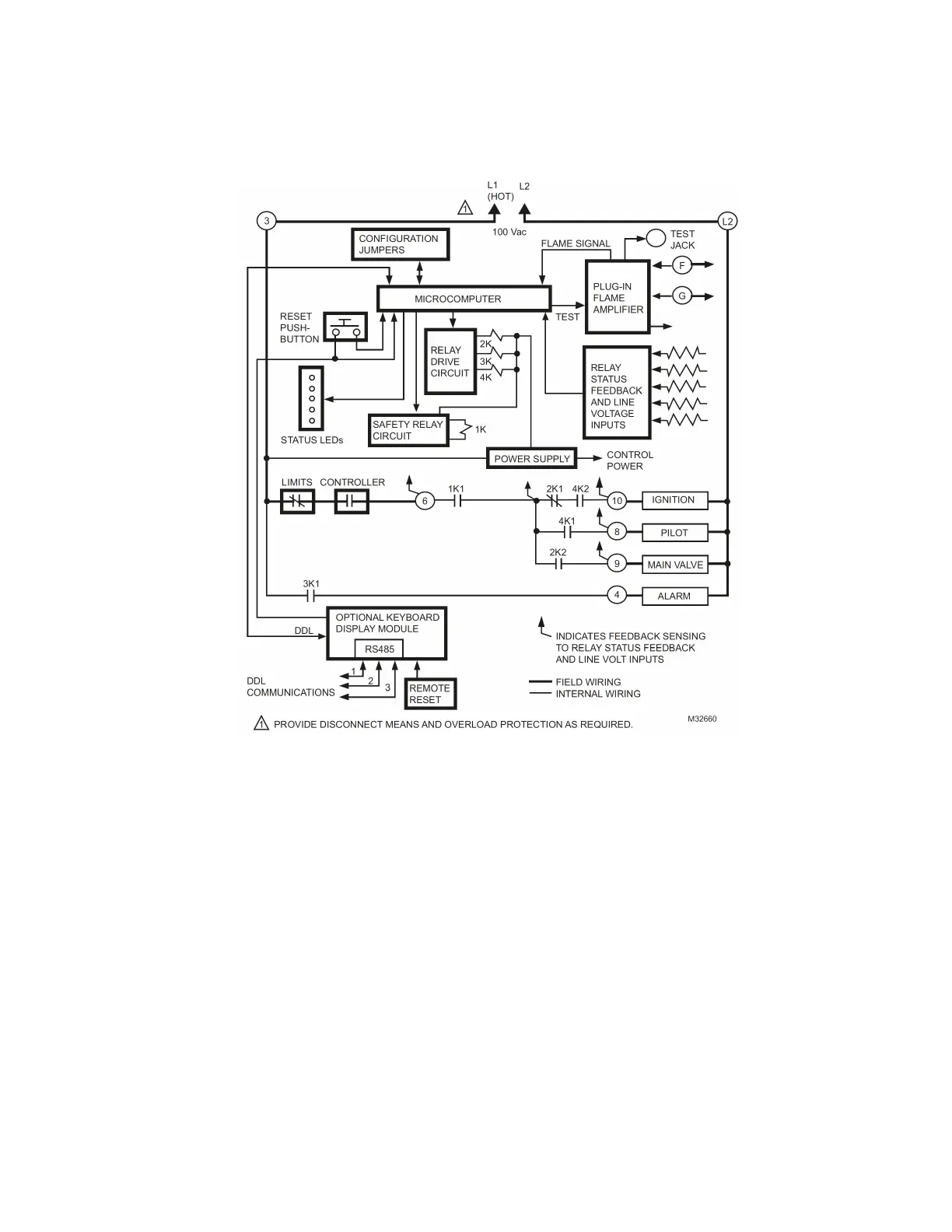
Fig. 4. Internal block diagram of the RM7890 (see Fig. 6 for detailed wiring instructions).
9 32-00216-01

Questions and Answers:

Question and Answer IconNeed help?

Do you have a question about the Honeywell RM7890 and is the answer not in the manual?

Honeywell RM7890 Specifications

General IconGeneral
BrandHoneywell
ModelRM7890
CategoryControl Unit
LanguageEnglish

Related product manuals