7 EN2R-9053 0408R11-NE
CONNECTION DIAGRAM
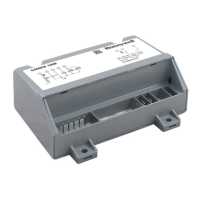
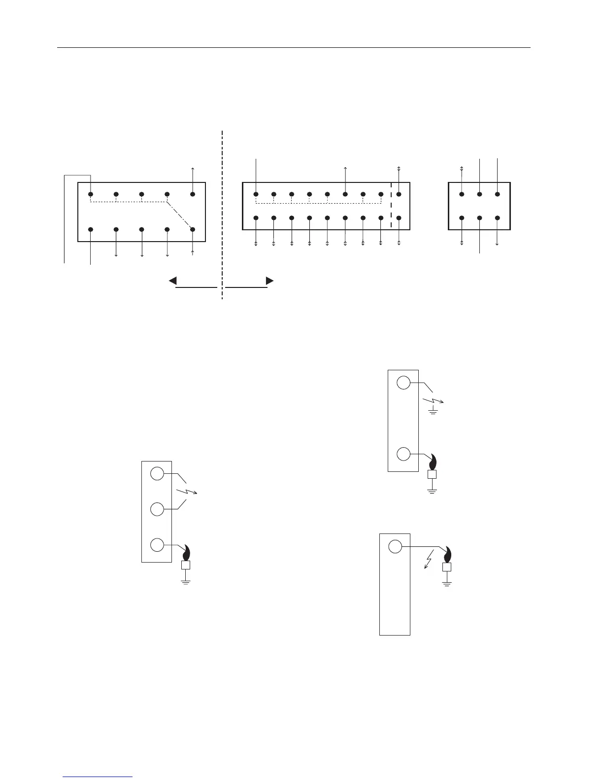
Fig. 1. General connection diagram CVBC
Due to software parameters and hardware jumpers,
specific configurations can be made.
See OS# specific connection diagram !
Connection diagram is mounted on the back of the
housing
IN/OUT can only be configured as input or output.
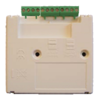
Fig. 2. Side connection CVBC for closed loop sparking
Fig. 3. Side connection CVBC for sparking to ground
Fig. 4. Side connection CVBC for combined ignition and
flame sensing
N
COM / GND
Tx
1
L
6
4
Rx
1
1*
10*
18*
9*
out
in / out
out
out
in / N
out
out
in / out
in / out
in / out
in / out
in / out
in / out
in / out
in / out
in / out
in / out
in / out
COM / GND
Vdc (output)
1*
9
8*
16*
6
3
5
10
Safety Extra Low Voltage (SELV)
230Vac
* : depending on OS number
 Loading...