EasyManua.ls Logo

Honeywell GENT S4-34410 User Manual

Honeywell GENT S4-34410
8 pages
To Next Page IconTo Next Page
Page #1 background imageLoading...
Page #1 background image
These instructions cover the above interface
modules and accessories. The S4 interface
modules are designed for use with Vigilon and
34000 fire alarm control panel. Each module
includes a loop isolator for device isolation.
Each interface module use one of 207 available
device addresses on a loop and responds to
regular polls from the control panel reporting the
type of device and the status (open/normal/short) of
its supervised input circuit(s).
Features
¨
Analogue addressable communications
¨
Built-in type identification automatically identifies
these devices to the control panel
¨
Reliable communication technique with high
noise immunity
¨
Soft or SAFE addressing
¨
Common mounting options including surface
mount, panel mount and DIN rail mount
¨
Dual-colour LEDs
¨
Plug-in terminal connections for ease of field
wiring
¨
EN54-17:2005 and EN54-18:2005
Cables
The cables recommended for wiring the input /
output lines are the same as those used for loop
wiring, see instructions supplied with the fire control
panel.
Installation
The S4 interface modules can be mounted in other
equipment housings using the DIN rail mount
brackets (S4-34491). A module can also be fitted
into a plastic box (S4-34490) or metal box
(S4-34492). The boxes have cable termination
points on the enclosure for incoming cables.
4188-873_issue 4_Pt.1_02/09_S4 LV Interfaces 1
Data and Installation
Interface Modules for Vigilon
Low voltage (LV) Input/Output
by Honeywell
S4-34410
S4 1-Input Interface
Module
(low voltage)
S4-34420
S4 1-Output &
1-Input Interface
Module (low voltage)
S4-34450
# S4 4-Input / Output
Interface Module
(low voltage)
L1
L2
0V
0V
Channel 1
Channel 2
Channel 3
Channel 4
L1
L2
0V
0V
NC
Input
L1
L2
0V
0V
Input
COM
NO
Output
S4-34490
Plastic box
1- End-of-line
Capacitor unit
2- 10K Resistors
2- 10K Resistors
1- End-of-line
Capacitor unit
8- 10K Resistors
S4-34491
DIN rail mount
bracket
# Now supplied full
y
assembled
1- Allen key
2 - M4 Screws
S4-34492
Metal box
2 - M4 Posi Pan Screws
7 - Hole plugs
Module
DIN rail mount bracket
Slide &
lock
Hook and push
to lock
DIN rail
Connect to loop
cable screen
Allen
key
Box
Module
M4 Screws
Door
64106
62.5
62.5
3 - box fixing points
(Includes 1-keyhole)
7 - top cable
entry points
Module
M4 Screws
Lid
80
140
Metal
backbox
7 usable cable entr
y
points
Question and Answer IconNeed help?

Do you have a question about the Honeywell GENT S4-34410 and is the answer not in the manual?

Honeywell GENT S4-34410 Specifications

General IconGeneral
BrandHoneywell
ModelGENT S4-34410
CategoryControl Unit
LanguageEnglish

Summary

Interface Modules: Features and Description

Interface Module Types

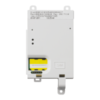
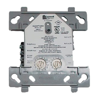
Illustrates and briefly describes the S4-34410, S4-34420, and S4-34450 interface modules.

Key Features

Highlights core capabilities including analogue addressable communications and dual-colour LEDs.

Cable Recommendations

Specifies recommended cables for input/output lines, matching those used for loop wiring.

Installation and Wiring

Mounting Options

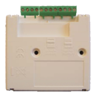
Details common mounting options including surface, panel, and DIN rail mounts for modules.

Wiring Diagrams

Provides detailed connection diagrams for S4 1-Input, S4 4-Input/Output, and S4 1-Output & 1-Input modules.

Technical Data and Specifications

Module Specifications

Details technical data including approval, weight, temperature, emission, immunity, and ingress protection.

Input/Output Modes

Explains input modes (Zone, Switch) and output modes (Relay, LED) with associated parameters.

Commissioning and Configuration

Configuration Process

Guides users on configuring S4 interface modules using the Commissioning Tool software v1.21.

Channel Mode Settings

Details configuration options for module channels: Unused, Output, Supervisory, Fault, and Fire inputs.

Zone Input (Zone I/P) Configuration

Explains how to configure Channel 1 as a Zone Input for conventional detectors and call points.

Confirmation Input/Output Configuration

Describes setting up channels for Confirmation Output (O/P) and Confirmation Input (I/P) functions.

Related product manuals