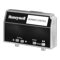
7800 SERIES S7800A KEYBOARD DISPLAY MODULE
65-009
0-6
12
Table 4. Expanded An
nunciato
r
.
Selectable Message
a
(Second Line)
Display Value (Second Line) First Line Message
Expanded Annunciator
Expanded Annunciator (EA not
connected)<
EA
Current Status (CS:)
a
EA Message< EA
Valve Closure (Valve Close) T5 = 1 or 0< EA
Burner Switch (Burner Sw.) T5 = 1 or 0< EA
Operating Control (OperControl) T6 = 1 or 0< EA
Auxiliary Limit (Aux Limit 1) T7 = 1 or 0< EA
Auxiliary Limit (Aux Limit 2) T8 = 1 or 0< EA
Low water Cutoff (LWCO) T9 = 1 or 0< EA
High Limit (High Limit) T10 = 1 or 0< EA
Auxiliary Limit (AuxLimit 3) T11 = 1 or 0< EA
Oil Selection Switch (Oil Select) T12 = 1 or 0< EA
High Oil Pressure Switch (Hi OilPres) T13 = 1 or 0< EA
Low Oil Pressure Switch
(LowOilPres)
T14 = 1 or 0< EA
High Oil Temperature Switch (Hi
OilTemp)
T15 = 1 or 0< EA
Low Oil Temperature Switch
(LowOilTemp)
T16 = 1 or 0< EA
Atomizing Switch (Atomize Sw) T19 = 1 or 0 EA
Gas Selection Switch (Gas Select) T17 = 1 or 0< EA
High Gas Pressure Switch (Hi
GasPres)
T18 = 1 or 0< EA
Low Gas Pressure Switch
(LowGasPres)
T19 = 1 or 0< EA
Airflow Switch (Airflow Sw) T20 = 1 or 0< EA
Auxiliary Interlock (Aux ILK 4) T21 = 1 or 0< EA
Auxiliary Interlock (Aux ILK 5) T22 = 1 or 0< EA
EA Fault Code nnn< EA
Software Revision (SW Rev.) nnnn< EA
a
See Table 8 for optional messages.
TROUBLESHOOTING
After the KDM is installed, return the 7800 SERIES to normal
operation, restore power and run the system through at least
one complete automatic cycle. For complete Troubleshooting
and System Checkout information, see form 65-0229.
7800 SERIES System Diagnostics
Troubleshooting control system equipment failures is made
easier with the 7800 SERIES self-diagnostics and first-out
annunciation. The S7800 provides visual annunciation by
displaying a fault code and fault or hold message on the
display.
Self-diagnostics of the 7800 SERIES enables it to detect and
annunciate both external and internal system problems.
Internal faults and external faults such as interlock failures,
flame failures and false flame signals are annunciated by the
KDM via the 7800 SERIES Relay Module.
The KDM displays a sequence status message indicating
STANDBY, PREPURGE, PRE-IGNITION, SAFETY 1, PILOT
IGN, PILOT STAB., MAIN IGN, RUN or POSTPURGE, as
appropriate. The selectable messages also provide visual
indication of current status and historical status of the
equipment, such as: Flame Signal, Total Cycles, Total Hours,
Fault History, Diagnostic
Information and Expanded
Annunciator terminal status (if used). With this information,
most problems can be diagnosed without extensive
trial-and-error testing.
Table 21 provides the sequence and status hold messages.

 Loading...