7800 SERIES S7800A KEYBOARD DISPLAY MODULE
25
65-009
0-6
APPENDIX A
Display Setup
The S7800A Keyboard Display Module (KDM) requires a
password to enter the Display Setup Menu.
DISPLAY Setup will appear. If you have a personal password,
enter it to enter Setup.
The Display Setup Menu offers the following functions:
-
Clone-Allows
the current display setup to be copied
entirely to another display (Series 3 or grea
te
r)-p
age
25.
-
MB
Address-Enables
the ModBus Feature and Loca-
tion. The 7800 SERIES device is located on the Mod-
Bus highway. It also provides a means of system
verification that ModBus is active and that this module
is being addressed
-p
age 26.
DISPLAY
Setup
± PASSWORD: 000
BACK
Edit:
- +
ENTER
M22890
-
MB
Baud-Sets
the data Transmit/Receive rate. The
S7800 is operating on
ModBus-page
27.
-
Clear All
-
Resets the Display settings back to the
factory
settings-page
27.
-
Password-Change
current default password of 000
to
a unique one the customer has sele
cte
d
-p
age 27.
-
CS
On/Off-Allows
the Customer Service message to
be displayed or the lockout message to be displayed
-
page 31.
-
CS
Test-Allows
the Customer Service message to be
viewed for accuracy. This will display just
once-p
age
31.
-
CS
Edit-Allows
for personalizing a Customer Service
message. Three screens of messages are available.
Each screen has two lines with 20 characters available.
See Table 9 for available character
text-page
37.
Display
Setup-CLONE
CLONE allows copying your entire Custom Display to
additional displays, Series 4 or higher.
Before you begin, you will want to build a cloning jig.
MASTER
SLAVE
Fig. 21. Display Setup screen.
Press ENTER by pressing the two ENTER buttons at the same
time.
Select
Exit
Fig. 22. Select/Exit screen.
Choose Select.
DISPLAY
Setup
Select:
CLONE
Fig. 23. Display Setup/CLONE screen.
Press ENTER by pressing the two ENTER buttons at the same
time. The Select/Exit Screen (see Fig. 22) will appear. Choose
Select.
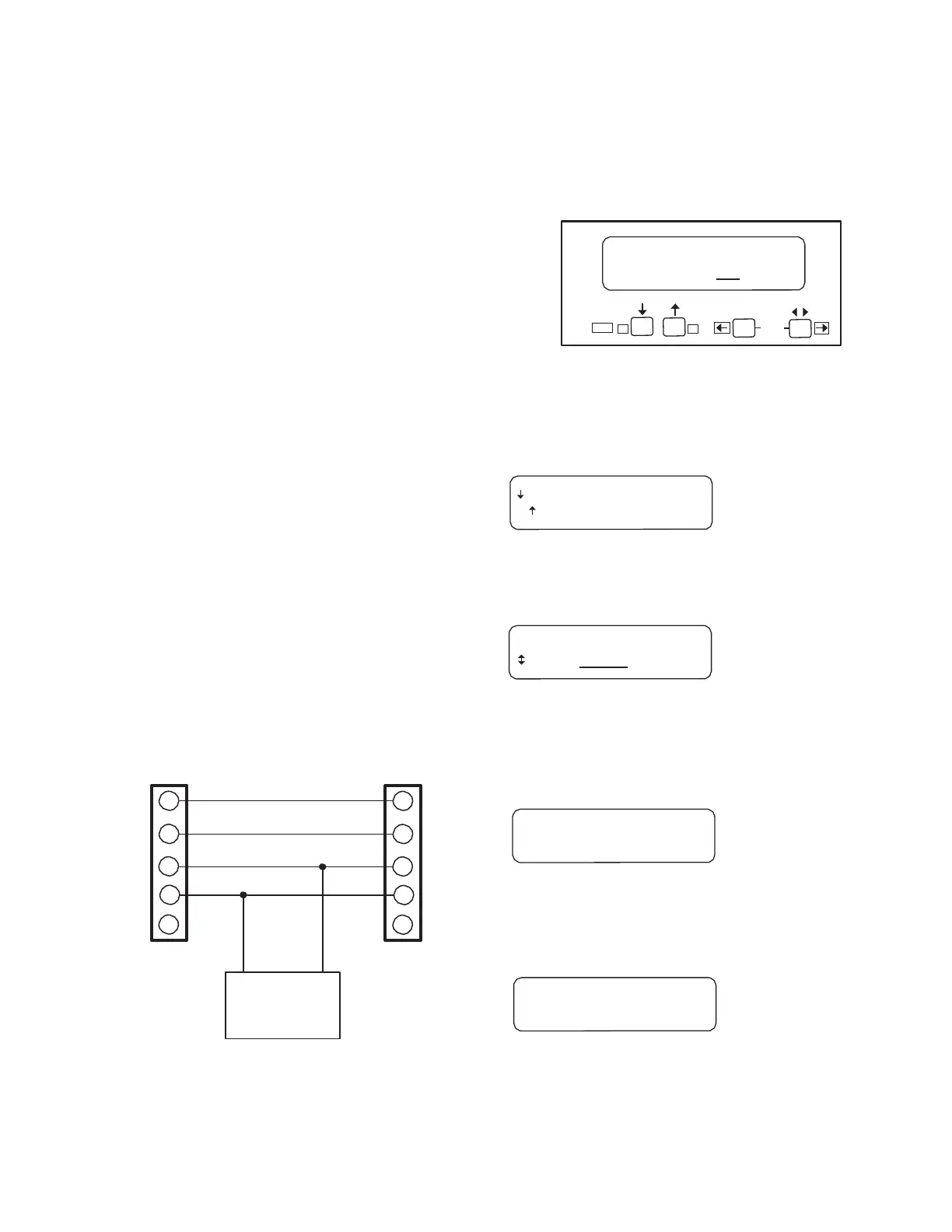
1
2
3
4
5
203541 FIVE-WIRE
CONNECTOR
+
_
13 VDC POWER
SUPPLY (203968
FOR EXAMPLE)
Fig. 20. Cloning
jig.
1
2
3
4
5
203541 FIVE-WIRE
CONNECTOR
M22880
Clone Master: I
am
T
ransmitting.
Fig. 24. Clone Master screen.
The Slave display will change from Fig. 25 to many On/Off
sweeps with periods of bright characters.
Waiting
for
Connection
. . .
Fig. 25. Waiting for Connection screen.
When complete, the Slave will still be going on and off, but the
To access the CLONE menu:
Press the left three buttons of the KDM for one second, then
release.
Cloning Complete screen can be read (Fig. 26). Replace this
Slave with additional displays that need to be cloned.