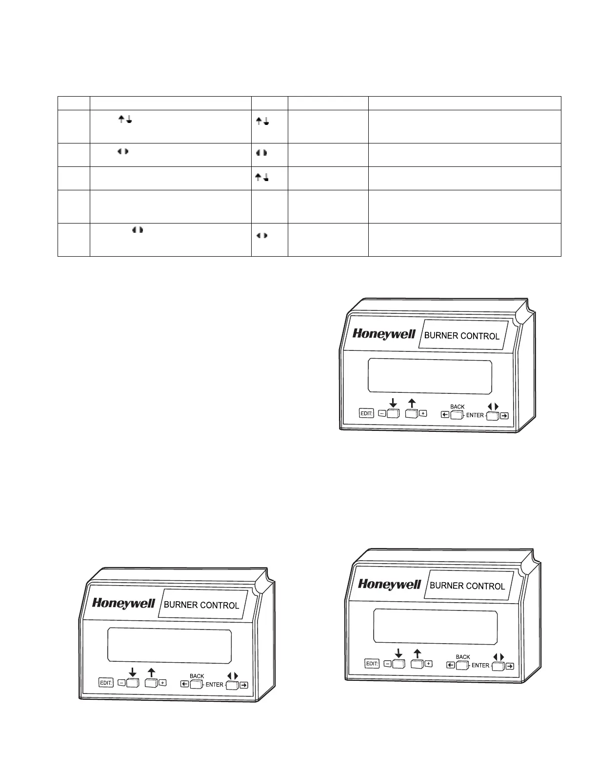
7800 SERIES S7800A KEYBOARD DISPLAY MODULE
15
65-009
0-6
Condition
at
the
time of
lockout
...
LOCKOUT
23p
*Airflow
Sw
.*
Table 6. Accessing Historical and Diagnostic Selectable Messages.
Step
Op
erat
ion
Press Display Comments
1.
Press
keys to access Diagnostic
Information.
STANDBY
Diagnostic Info>
Use the Down/Up SCROLL keys to access the
selectable message. The second line will display
Diagnostic Information.
2. Press key to Access Diagnostic
Information.
STANDBY
Diagnostic Info>
Use the Change Level key to access the
Diagnostic Information.
3. Continue display of Diagnostic
Information.
STANDBY
¡¿
DI
Device RM7800<
Push the SCROLL key to scroll to the next
Diagnostic Message.
4. Continue through remaining Diagnostic
Information display following step 3 as
required.
-
-
-
5. Press the key to return to the first
level of Diagnostic Information data
prompt or to other selectable messages.
STANDBY
Diagnostic Info>
Another display can be selected or discontinue
accessing Diagnostic Information review.
SERVlCE NOTE: If the Keyboard Display Module screen is
scrambled, remove and reinstall the Keyboard
Display Module and reset the 7800 SERIES Relay
Module.
2. State 2 (Fig. 17). Display of the second state message
lasts two seconds.
SERVlCE NOTE: Reset the 7800 SERIES Relay Module by
pressing the reset push button on the relay module or
pressing a remote reset push button wired through
the Keyboard Display Module, Data ControlBus™
Module or Remote Reset Module. A power-up reset
will cause an electrical reset of the 7800 SERIES
Relay
Module but will not reset a lockout condition.
Lockout Messages
When the 7800 SERIES is locked out, it displays a repeating
cycle of messages unless the Call Service Feature is Active.
Then the Fault message is displayed followed by the Customer
Service message. The Fault History is NOT available if the Call
Service is Active. See Table 7. There are four
states in the
cycle:
Fig. 17. Lockout message, State 2.
M22878
1. State 1 (Fig. 16). A first state message display lasts six
seconds. First line displays the word LOCKOUT followed
by the fault code number and possibly a lower case letter
if an Expanded Annunciator is connected. The letter
corresponds to the first-out code supplied by the
Expanded Annunciator. The lockout
reason
corresponding to the fault code number is displayed on
the second line, highlighted by asterisks on each side.
3. State 3 (Fig. 18). Display of the third state message lasts
three seconds. It is a replica of the burner status as it
existed at the time of the lockout. The second line is
blank if the burner status at the time of lockout did not
include a preemptive message
(in parentheses) for the
second line.
PURGE
(Airflow
Sw
.)
M22877
Fig. 18. Lockout message, State 3.
M22879
Fig. 16. Lockout message, State 1.