7800 SERIES S7800A KEYBOARD DISPLAY MODULE
35
65-009
0-6
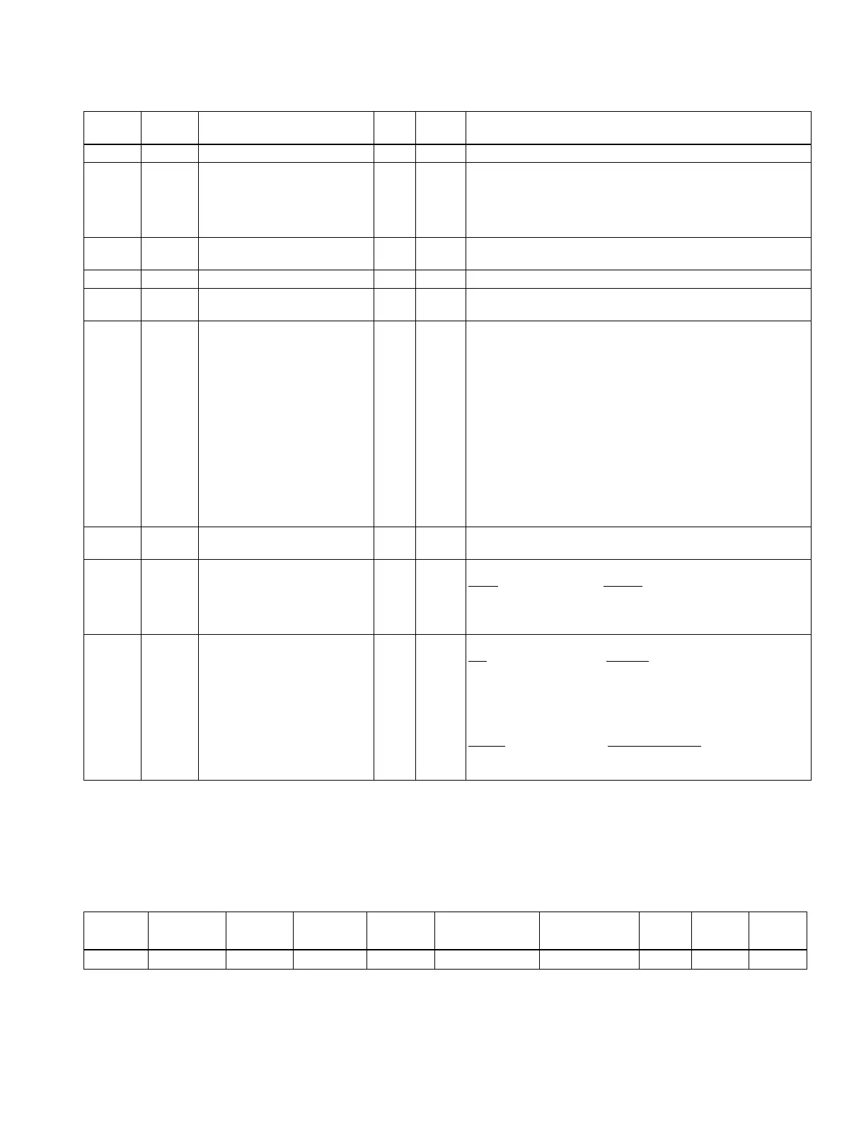
Table 16. ModBus™ Register Assignments. (Continued)
dd
ess
(hex)
Registe
(
d
ec)
Parameter Name
Read
Write
Format Notes
0066 40103 Post-Purge time R U16 Seconds
0067 40104 Valve P
oving Mode R U16 0 = Valve P
oving is not enabled
1 = Enabled before Run
2 = Enabled after Run
3 = Enabled before and after Run
4 = Enabled split half before and half after Run
0068 40105 Valve P
oving options R U16 1 = Uncommissioned
2 = Commissioned
0069 40106 Valve P
oving time R U16 Seconds
0066-
007E
40103-
40127
Unused
007F 40128 BC Remote Command R/W U16
Only one bit
in
the LSByte must
be
set,
ith
the exception
of bit 15:
Bit 0 =Revert to autonomous operation.
Bit 1 = Don't fire, remain off.
Bit 2 = Go to Hi Fire during Run.
Bit 3 = Go to Lo Fire during Run.
Bit 4 = Remote reset.
a
Bits 5-7 must be 0.
Bits 8-14 are ignored.
Bit 15: Copied to the control status register. The remote
control status register can be used to verify operation of the
command.
Bits 1-3 must be refreshed at least every 120 seconds, but
not more than once a second, for the burner control to
remain in the commanded state.
01B7-
01B8
40440-
40441
Unused
U32
01BA 40443 Device Da
a Ready
U16 Device da
a was properl
eceived b
S7800.
Bit(s) Device
0 RM78XX
3 EC78XX
4-15 Unused
01BB 40444 S7800 Device Compatibility
with Current Software
Revision
S7800 Software Revision
Compatibility with Legacy
Software Revisions.
U16 Device is compatible
ith the S7800 version.
Bit
Device
0 RM78XX
3 EC78XX
4-7 Unused
Used for indication of S7800 revision compatibility.
Bit(s) Compatible with:
8 Series 2
9-15 Future
NOTE: "Device Data Ready" and "S7800 Compatibility" bits can be used to quickly check device availability and compatibility
then read/write registers of only these devices.
Response Message Format for Function Code 17.
This format is device specific and is only available for the 7800
SERIES burner control. See Table 17.
Table 17. Response Message Format for function code 17 (11h), (26 bytes).
Sla
ve
Address
Function
Code
Byte Count Slave lD
a
Run
lndi
cator
Stat
u
s
b
Device
Descr
iption
c
N/A
CRC CRC
Byte 0 1 2 3 4 5-15 16-23 24 25
a
Slave ID: Always 0x78 when using RM78xx or EC78xx Relay Modules(1 byte) (byte 3).
b
Run Indicator Status: Always FF=ON (one byte) (byte 4).
c
Device Description: 16 Character ASCII OS number for the Burner Control (11 bytes) (bytes 5-15).