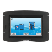
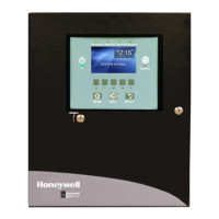
S7999D1048 COMBUSTION SYSTEM OPERATOR INTERFACE DISPLAY
65-0321—01 46
Fig. 105. Trend Analysis Data Displayed in Seconds.
Trend analysis data can be cleared, by the user. After the data
is cleared the trend graph begins with new sample data.
The Trend Analysis data can also be saved to the S7999D (a
Trend Analysis keyboard screen will be displayed for the user
to enter a name for the trend analysis data), the saved trend
data can then be viewed, renamed, deleted or copied to a USB
memory stick.
The following table lists which sensor inputs are sampled.
NOTE: Not all data is sampled per controller. Some data
input is dependent on the UDC controller model.
For example, a PID Load controller provides water
temperature or steam pressure input, but not
both, based on the UDC controller model.
UDC controllers that can have more than one con-
current sensor input, such as the Steam/Fuel
Flow Monitor, only display one of the sensors at a
time. The user decides which sensor input data to
view.
The user can select which status from the UDC controller
status page to display on the Local Home page, if any, on the
UDC controller status page.
Stack Temperature Controller
The current stack temperature is obtained from the UDC
controller and displayed in text value and in a bar graph on the
page. Upper and lower limits of the stack temperature range
are displayed on the page next to the temperature bar graph.
Fig. 106. Stack Temperature Controller.
If a High Temperature alarm is configured in the UDC
controller, the alarm is displayed on the page along with the
current alarm setpoint. An LED displayed on the page indicates
whether the alarm is active (red) or inactive (green).
If a High Temperature alarm is configured in the UDC
controller, the user can adjust the setpoint.
If an FGR Permissive alarm is configured in the UDC controller,
the alarm setpoint setting is displayed on the page, and the
user can adjust the setpoint. An LED displayed on the page
indicates whether FGR is permissive (green) or not (red).
Table 6. Trend analysis controller source data
UDC controller Data Input
Stack Temperature controller Stack temperature
PID Load controller Water temperature
PID Load controller Steam pressure
Feed Pump Level controller Vessel level
Steam/Fuel Flow Monitor Steam flow rate
Steam/Fuel Flow Monitor Gas flow rate
Steam/Fuel Flow Monitor Fuel oil flow rate
Steam/Fuel Flow Monitor Total steam flow
Steam/Fuel Flow Monitor Total gas flow
Steam/Fuel Flow Monitor Total fuel oil flow
Thermal Shock controller Water supply temperature
 Loading...