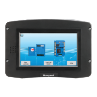
S7999D1048 COMBUSTION SYSTEM OPERATOR INTERFACE DISPLAY
65-0321—01 58
R7999 OUTPUTS AND INPUTS
The current state of the R7999 outputs and inputs are displayed on the Monitor screen for convenience and diagnostics purposes.
The inputs and outputs are defined as follows:
Table 8. Outputs.
Table 9. Inputs.
UDC CONTROLLER APPLICATION
UDC Controller Interface
The UDC controllers interface to the S7999D via the COM 2 port. The following interface requirements must be specified in the
Communications group of the UDC controller.
The Modbus™ address setting in ComADR determines the
UDC controller application type. Careful assignment of
Modbus™ addresses to UDC controllers and S7810M devices
is necessary so that duplicate addresses aren’t used.
The following application notes describe how the UDC
controller is configured to perform different functions in a
burner/boiler system. Using the UDC controller models and
recommended sensor types for each application is critical to
the success of the application. These application notes only
provide an introduction to the setup needed. More detailed
information for UDC controller setup should be obtained from
the appropriate UDC documentation (see Installing the
Hardware).
UDC controller parameters applicable for each application are
listed, and recommended settings for typical variants of the
application are provided.
Abbreviation Description Meaning when ON
LCO Limit Control Output Limits are satisfied and demand exits. The R7999 is operational and able to move all
actuators.
HFP High Fire Proved The R7999 has moved the actuators to the Purge position.
LFP Low Fire Proved The R7999 has moved the actuators to the Lightoff position.
Fuel 1 Fuel Select Channel 1 Fuel 1 is selected.
Fuel 2 Fuel Select Channel 2 Fuel 2 is selected.
ALM Alarm The system is in an alarm state.
Abbreviation Description Meaning when ON
LCI Limit Control Input Limits are satisfied and demand is present.
HF High Fire Input R7999 is being commanded to drive actuators to the Purge position.
LF Low Fire Input R7999 is being commanded to drive actuators to the Lightoff position
MV Main Valve Input The main valve input is active. Normally only active during “Run,” and transitional with LF
during lightoff.
Table 10. UDC Controller Communication Interface .
Parameter Setting Comment
ComADR 10-19=Stack Temperature
20-29=Water Temperature PID Load Control
30-39=Steam Pressure PID Load Control
40-49=Feed Pump/Level Control
50-59=Steam/Gas Flow Monitor
60-69=Steam/Fuel Oil Flow Monitor
70-79=Thermal Shock
Modbus™ slave address
COMSTA MODB Modbus™ communication
IRENAB ENAB Enable infrared communication port
BAUD 19.2K 19200 bps
TX_DLY 1 Response delay = 1 ms
WS_FLT FP B Floating point data order
SDENAB DIS Disable shed functionality
UNITS EGR Data specified in engineering units
CSRATIO 1 Computer setpoint ratio
CSP BI 0
LOOPBK DIS Disable loopback test
 Loading...