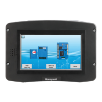
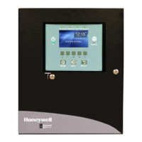
S7999D1048 COMBUSTION SYSTEM OPERATOR INTERFACE DISPLAY
65-0321—01 8
Fig. 5. Example wiring diagram for one or more boiler
systems with UDC Controller.
Manual assignment of the UDC controllers to their associated
burner/boiler system is required to allow UDC controllers on
the S7810 Modbus™ network. No automatic assignment is
possible.
Careful Modbus™ addressing is required when inserting UDC
controllers in this configuration since duplicate addresses
aren't allowed. Default Modbus™ addresses for the UDC
controllers may need to be changed for them to work properly
in the network.
SYSTEM MODE
S7999D manages a series of (up to 99) local systems in a
S7999D Modbus™ network (see Fig. 8). In the System
configuration, Modbus™ addresses of the nodes are learned
by the System S7999D, so manual assignment isn’t necessary.
Be sure not to duplicate Modbus™ addresses in the nodes.
UP TO A TOTAL OF 99 S7810M AND UDC CONTROLLERS CAN BE CONNECTED TO
THE S7999D. SEE 65-0249 AND UDC MANUALS FOR WIRING.
M33556
CONTROLINKS
CONTROLLER
R7999
A B C
A B C A B C COM POWER
S7999D OI DISPLAY
3
1
“C” TERMINALS ARE CONNECTED INTERNALLY TO 24 VAC “COM”.
3
4
MODBUS BAUD RATE MUST BE SET FOR EITHER 9600 0R 19200 BAUD RATE.
5
SEE 65-0238 FOR R7999 WIRING.
6
120 Ω, 1/4 WATT RESISTOR BETWEEN TERMINALS A AND B OF THE MODBUS AT
THE FARTHEST S7810M MAY BE NECESSARY FOR LONG RS-485 RUNS.
7
CONNECT SHIELD TO EARTH GROUND.
1
SEE 65-0249 FOR CONTROL BUS (LOCAL RS-485 COMMUNICATION BUS) WIRING.
2
1
COM 1
COM 2
24 VAC
3
S7810M
MODBUS
MODULE
B
A
C
8
7
6
2
4
UDC
CONTROLLER
D-
D+
SHLD
16
17
18
5 7
 Loading...