SCS Series Manual — P/N 15712:L 7/18/16 155
HVAC Wiring Diagrams Ratings and Wiring Diagrams
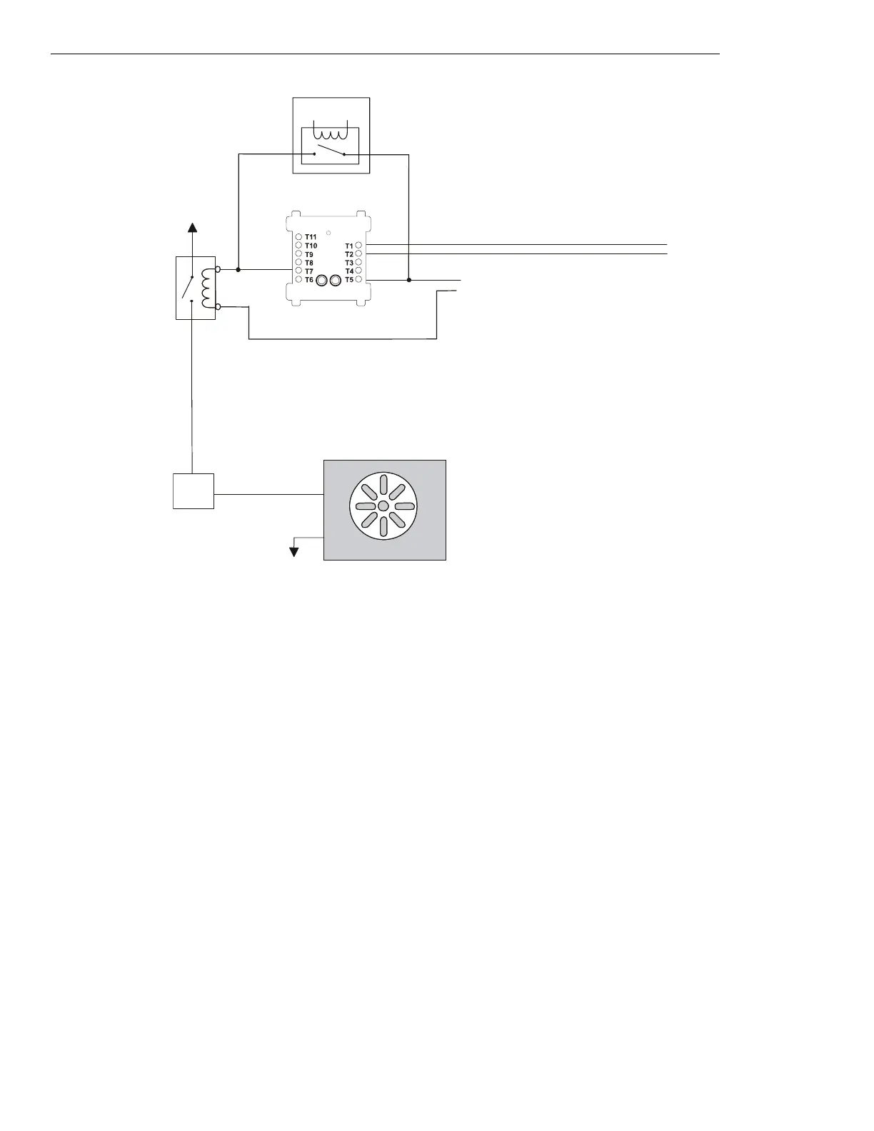
Figure 5.46 Fan Control - HVAC Switch Group Type 8
Figure 5.46 depicts a fan in an HVAC system with the capability of
ON control, switch group type 8. In the above configuration, the
CON
ON⁄OP
CM is deactivated. The CON
ON⁄OP
CM is wired in parallel with the EMS. (When wired in parallel with the EMS, use a relay
module.) When the CON
ON⁄OP
CM is deactivated, the EMS is free to control the fan. In this case the EMS is OFF, so no power is being sup-
plied to the fan. When no power is supplied to the fan, the fan is
OFF. When the CON
ON⁄OP
CM is activated, the CON
ON⁄OP
CM overrides
whatever state the EMS is in and closes the normally open contactor, thus supplying power to the fan and turning it on.
FRM-1
COM
N/O.
Power Source
1a listed
contactor
Service
Disconnect
Switch
Power Return
fan-h8-fs-2.wmf
SLC Loop
FAN OFF
Listed
24 VDC
Power Source
CON
ON/OP
CM
(deactivated)
Energy Management System
*If the SLC device
does not match the
one in this figure,
refer to the SLC
manual appendix,
which contains wiring
conversion charts for
type V and type H
modules. e
 Loading...