SDC Connection of Room Devices
MU1H-0438GE51 R0313 39
8.2 Wall Module TF 22 / TFU 22
Configuration
Configuration and allocation is done via parameter 08, 09 or 10 in
the “Hydraulic” menu.
For any of the signals "Room temperature" and "Setpoint" one
variable input must be assigned.
The parameter setting in the “Hydraulic” menu for room sensor is
30 (for direct heating circuit), 31 (for mixing circuit 1) or 32 (for
mixing circuit 2).
The parameter setting in the “Hydraulic” menu for “Setpoint
deviation” and “Operating mode” is 50 (for direct heating circuit),
51 (for mixing circuit 1) and 52 (for mixing circuit 2).
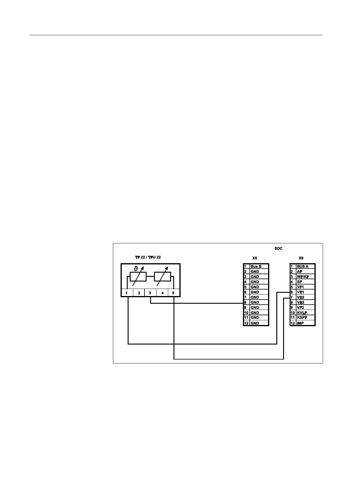
Electrical connection occurs according to the assignment to
variable input 1 (VE1) ... variable input 3 (VE3) (Wall socket).
Example: Assignment of TF 22 to mixing circuits 1 (room sensor
to VE1 and setpoint / operating mode to VE2)
1 Actual value
3 GND
5 Setpoint and operating mode