SPYDER® LON PROGRAMMABLE, VAV/UNITARY CONTROLLERS
5 63-2685—03
Before mounting the actuator onto the VAV box damper shaft,
determine the following:
1. Determine the damper shaft diameter. It must be
between 3/8 in. and 1/2 in. (10 to 13 mm).
2. Determine the length of the damper shaft. If the length of
the VAV box damper shaft is less than 1-9/16 in.
(40 mm), the actuator cannot be used.
3.
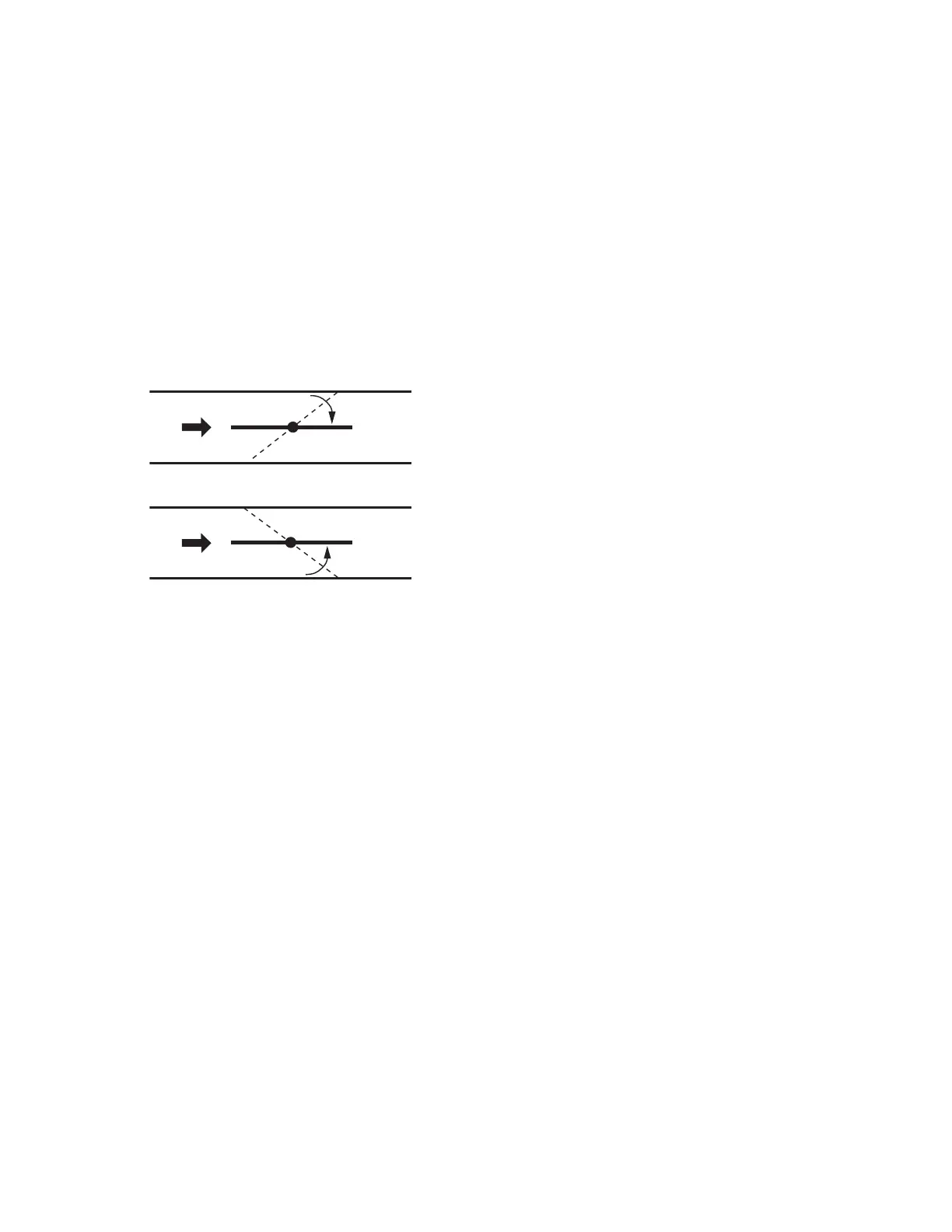
Determine the direction the damper shaft rotates to open
the damper (CW or CCW) (see Fig. 3). Typically, there is
an etched line on the end of the damper shaft that indi-
cates the position of the damper. In Fig. 2, the indicator
shows the damper open in a CW direction.
4. Determine the damper’s full opening angle (45, 60, or 90
degrees). In Fig. 2, the damper is open to its full open
position of 90 degrees.
Fig. 3. Determining the rotation direction (CW or CCW)
for damper opening.
Mounting Actuator Onto Damper Shaft
(PVL0000AS, PVL4022AS, and PVL6436AS )
The unit is shipped with the actuator set to rotate open in the
clockwise (CW) direction to a full 95 degrees. The extra 5
degrees ensures a full opening range for a 90 degree damper.
The installation procedure varies depending on the damper
opening direction and angle:
1. If the damper rotates clockwise (CW) to open, and the
angle of the damper open-to-closed is 90 degrees:
a. Manually open the damper fully (rotate clockwise).
b. Using the Declutch button, rotate the universal shaft
adapter fully clockwise.
c. Mount the actuator to the VAV damper box and shaft.
d. Tighten the two bolts on the centering clamp
(8 mm wrench; 70.8–88.5 lb-in. [8–10 Nm] torque).
When the actuator closes, the damper rotates CCW
90 degrees to fully close.
2. If the damper rotates clockwise (CW) to open, and the
angle of the damper open-to-closed is 45 or 60 degrees:
a. Manually open the damper fully (rotate clockwise).
b. The actuator is shipped with the mechanical
end-limits set at 95 degrees. Adjust the two
mechanical end-limit set screws to provide the
desired amount of rotation. Adjust the two set screws
closer together to reduce the rotation travel.
c. Tighten the two mechanical end-limit screws (Phillips
#2 screwdriver; (26.5–31 lb-in. [3.0–3.5 Nm] torque).
d. Using the Declutch button, rotate the universal shaft
adapter fully clockwise.
e. Mount the actuator to the VAV damper box and shaft.
f. Tighten the two bolts on the centering clamp
(8 mm wrench; 70.8–88.5 lb-in. [8–10 Nm] torque).
g. When the actuator closes, the damper rotates CCW
either 45 or 60 degrees to fully close.
3.
If the damper rotates counterclockwise (CCW) to open, and
the angle of the damper open-to-closed is 90 degrees:
a. Manually open the damper fully (rotate counterclock-
wise).
b. Using the Declutch button, rotate the universal shaft
adapter fully counterclockwise.
c. Mount the actuator to the damper box and shaft.
d. Tighten the two bolts on the centering clamp (8 mm
wrench; 70.8–88.5 lb-in. [8–10 Nm] torque). When
the actuator closes, the damper rotates CW
90 degrees to fully close.
4.
If the damper rotates counterclockwise to open, and the
angle of the damper open-to-closed is 45 or 60 degrees:
a. Manually open the damper fully (rotate counterclock-
wise).
b. The actuator is shipped with the mechanical
end-limits set at 95 degrees. Adjust the two
mechanical end-limit set screws to provide the
desired amount of rotation. Adjust the two set screws
closer together to reduce the rotation travel.
c. Tighten the two mechanical end-limit screws
(Phillips #2 screwdriver; (26.5–31 lb-in. [3.0–3.5 Nm]
torque).
d. Using the Declutch button, rotate the universal shaft
adapter fully counterclockwise.
e. Mount the actuator to the VAV damper box and shaft.
f. Tighten the two bolts on the centering clamp
(8 mm wrench; 70.8–88.5 lb-in. [8–10 Nm] torque).
g. When the actuator closes, the damper rotates CW
either 45 or 60 degrees to fully close.
IMPORTANT
Special precautions must be taken for dampers that
open in a CCW direction. The actuator is shipped with
its rotation direction set to CW to Open, which applies
to the damper direction in steps 1 and 2 above. If the
damper shaft rotates in the CCW direction to open,
the controller software must be programmed to
change the rotation to “Reverse to Open,” which
applies to the damper direction in steps 3 and 4
above.
IMPORTANT
It is advisable to leave the dampers in an open
position after installation to avoid the possibility of
over-pressurizing the duct work on fan startup. Use
the Declutch button (see Fig. 1 on page 4) to open the
box damper on controllers that are powered down, to
prevent over-pressurization in the duct work on fan
startup. To Declutch, press and hold the button to
disengage the motor. Turn the damper shaft until the
damper is open and release the button. When power
is restored to the controller, the controller
synchronizes the damper actuator, so that the
damper is in the correct position upon startup.
Mount Controller
NOTE: The controller may be wired before mounting to a
panel or DIN rail.
Terminal blocks are used to make all wiring connections to the
controller. Attach all wiring to the appropriate terminal blocks
(see “Wiring” on page 9).
See Fig. 4–Fig. 7 for panel mounting dimensions. See Fig. 8
on page 7 for DIN rail mounting.
AIR
FLOW
AIR
FLOW
CW TO OPEN, CCW TO CLOSE
CCW TO OPEN, CW TO CLOSE
M2067B
TYPE A DAMPER
TYPE B DAMPER
 Loading...