SPYDER® LON PROGRAMMABLE, VAV/UNITARY CONTROLLERS
21 63-2685—03
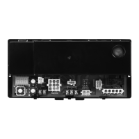
Fig. 24. Controller wiring diagram (model PUL6438S
shown) for RP7517B pneumatic transducer.
CHECKOUT
Step 1. Check Installation and Wiring
Inspect all wiring connections at the controller terminals, and
verify compliance with installation wiring diagrams. If any
wiring changes are required, first be sure to remove power
from the controller before starting work. Pay particular attention
to:
— 24 Vac power connections. Verify that multiple controllers
being powered by the same transformer are wired with the
transformer secondary connected to the same input
terminal numbers on each controller. Use a meter to
measure 24 Vac at the appropriate terminals (see Fig. 13 on
page 11). Controller configurations are not necessarily
limited to three devices, but the total power draw, including
accessories, cannot exceed 100 VA when powered by the
same transformer (U.S. only).
— Be sure that each controller has terminal 3 wired to a
verified earth ground, using a wire run as short as possible
with the heaviest gauge wire available, up to 14 AWG (2.0
sq mm) with a minimum of 18 AWG (1.0 sq mm) for each
controller in the group (see Fig. 13 on page 11).
— Verify that Triac wiring of the digital outputs to external
devices uses the proper load power and 24 Vac common
terminal (digital output common terminals) for High-Side
switching.
NOTE: All wiring must comply with applicable electrical
codes and ordinances or as specified on installation
wiring diagrams.
For guidelines for wiring run lengths and power budget, see
“Power” on page 7.
VERIFY TERMINATION MODULE PLACEMENT (MULTIPLE
CONTROLLERS ONLY)
The installation wiring diagrams should indicate the locations
for placement of the 209541B termination module(s). See
Fig. 14 on page 12 and refer to the “L
ONWORKS® Bus Wiring
Guidelines,” form 74-2865, and the “FTT Termination Module
Installation Instructions,” form 95-7554.
Correct placement of the termination module(s) is required for
proper L
ONWORKS® Bus communications.
Step 2. Startup
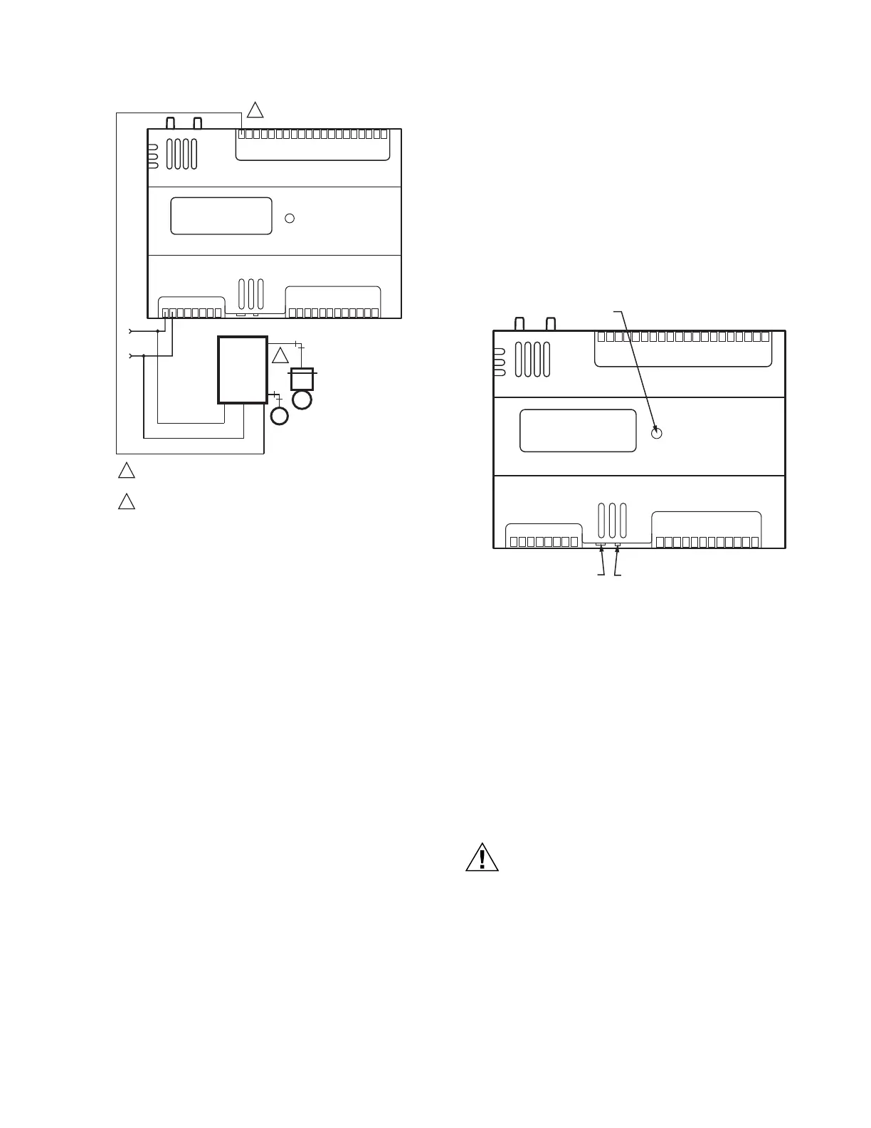
Refer to Fig. 25 and the following text for startup information.
Fig. 25. LED, service pin, and network
connection locations.
BROADCAST THE SERVICE MESSAGE
The Service Message allows a device on the L
ONWORKS® Bus
to be positively identified. The Service Message contains the
controller’s Neuron
®
ID number and node type. This is used to
confirm the physical location of a particular Spyder Lon device
in a building.
• To send the Service Message from the controller, press the
N
EURON® Service Pin pushbutton on the controller (see Fig.
25 above, and Fig. 16 and Fig. 17 on page 14). This button
sends out the Service Message when it is pressed,
regardless of the controller’s current mode of operation.
Equipment Damage Hazard.
Can cause controller damage or failure.
Do not use any metal object to press the N
EURON®
Service Pin. Use a plastic rod or wood device (such as
a pencil with the lead broken off) to press the pin. Using
a metal object can damage the circuitry of the
controller.
CONTROLLER STATUS LED:
The LED on the front of the controller provides a visual
indication of the status of the device. When the controller
receives power, the LED appears in one of the following
allowable states, as described in Table 8.
AO-1
COM
AO-2
AO-3
COM
UI-1
COM
UI-2
UI-3
COM
UI-4
UI-5
COM
UI-6
DI-1
DI-2
COM
DI-3
20V DC
DI-4
NET-2
NET-1
SHLD
EGND
24 VAC
24VAC COM
DO-1
COM
DO-2
DO-3
DO-4
DO-5
COM
DO-6
COM
1
2
3 4 5 6
7 8
1 0 9 2 3 4 5 6 7 8 0 9
1 1 1 1 1 1 1 1 1 2 1
1
2
3 4
5
6
7 8
0
9
2 2 2 2 2 2 2 2 2 3 3
1
2
3 4
5
6
7 8
0
9
3 3 3 3 3 3 3 3 4
M23570B
24 VAC
AO1
24 VAC
COM
PUL6438S
1
2
USE 1/4 IN (6 MM) PNEUMATIC TUBING. MINIMUM BRANCH LINE
MUST BE 6 FT. (1.8M) OR LONGER.
TERMINALS 21, 23, AND 24 ARE ANALOG OUTPUTS.
+
-
BLUE
BLACK
BROWN
PNEUMATIC
VALVE
ACTUATOR
RP7517B
1M
2B
M
2
1
DO-7
DO-8
COM
SBUS1
SBUS2
LONWORKS
®
BUS JACK
(LABELLED SRV JCK)
NEURON
®
SERVICE PIN
(LABELLED SRV PIN)
TERMINALS 1-8 TERMINALS 9-20
TERMINALS 21-40
AO-1
COM
AO-2
AO-3
COM
UI-1
COM
UI-2
UI-3
COM
UI-4
UI-5
COM
UI-6
DI-1
DI-2
COM
DI-3
20V DC
DI-4
NET-2
NET-1
SHLD
EGND
24 VAC
24VAC COM
DO-1
COM
DO-2
DO-3
DO-4
DO-5
COM
DO-6
COM
1
2
3 4 5 6
7 8
1 0 9 2 3 4 5 6 7 8 0 9
1 1 1 1 1 1 1 1 1 2 1
1
2
3 4
5
6
7 8
0
9
2 2 2 2 2 2 2 2 2 3 3
1
2
3 4
5
6
7 8
0
9
3 3 3 3 3 3 3 3 4
M23562B
DO-7
DO-8
COM
SBUS1
SBUS2

 Loading...