SPYDER® LON PROGRAMMABLE, VAV/UNITARY CONTROLLERS
63-2685—03 4
— Hardware driven by the analog current outputs must have a
maximum resistance of 550 Ohms, resulting in a maximum
voltage of 11 volts when driven at 20 mA. If resistance
exceeds 550 Ohms, voltages up to 18 Vdc are possible at
the analog output terminal.
Electrical Shock Hazard.
Can cause severe injury, death or property damage.
Disconnect power supply before beginning wiring or
making wiring connections to prevent electrical shock
or equipment damage.
INSTALLATION
The controller must be mounted in a position that allows
clearance for wiring, servicing, removal, connection of the
LonWorks® Bus Jack, and access to the Neuron® Service Pin
(see Fig. 16 and Fig. 17 on page 14).
The controller may be mounted in any orientation.
IMPORTANT
Avoid mounting in areas where acid fumes or other
deteriorating vapors can attack the metal parts of the
controller, or in areas where escaping gas or other
explosive vapors are present. Fig. 4–Fig. 7 on page 6
for mounting dimensions.
For PVL0000AS, PVL4022AS, and PVL6436AS models, the
actuator is mounted first and then the controller is mounted.
For the other models, go to “Mount Controller” on page 5 to
begin the installation.
Mount Actuator onto Damper Shaft
(PVL0000AS, PVL4022AS, and
PVL6436AS)
PVL0000AS, PVL4022AS, and PVL6436AS controllers include
the direct-coupled actuator with Declutch mechanism, which is
shipped hard-wired to the controller.
The actuator mounts directly onto the VAV box damper shaft
and has up to 44 lb-in. (5 Nm) torque, 90-degree stroke, and
90 second timing at 60 Hz. The actuator is suitable for
mounting onto a 3/8 to 1/2 in. (10 to 13 mm) square or round
VAV box damper shaft. The minimum VAV box damper shaft
length is 1-9/16 in. (40 mm).
The two mechanical end-limit set screws control the amount of
rotation from 12° to 95°. These set screws must be securely
fastened in place. To ensure tight closing of the damper, the
shaft adapter has a total rotation stroke of 95° (see Fig. 1).
NOTES:
1. The actuator is shipped with the mechanical end-
limit set screws set to 95 degrees of rotation.
Adjust the two set screws closer together to
reduce the rotation travel. Each “hash mark” indi-
cator on the bracket represents approximately 6.5°
of rotation per side.
2. The Declutch button, when pressed, allows you to
rotate the universal shaft adapter (see Fig. 1).
IMPORTANT
Determine the damper rotation and opening angle
prior to installation. See Fig. 2 and 3 for examples.
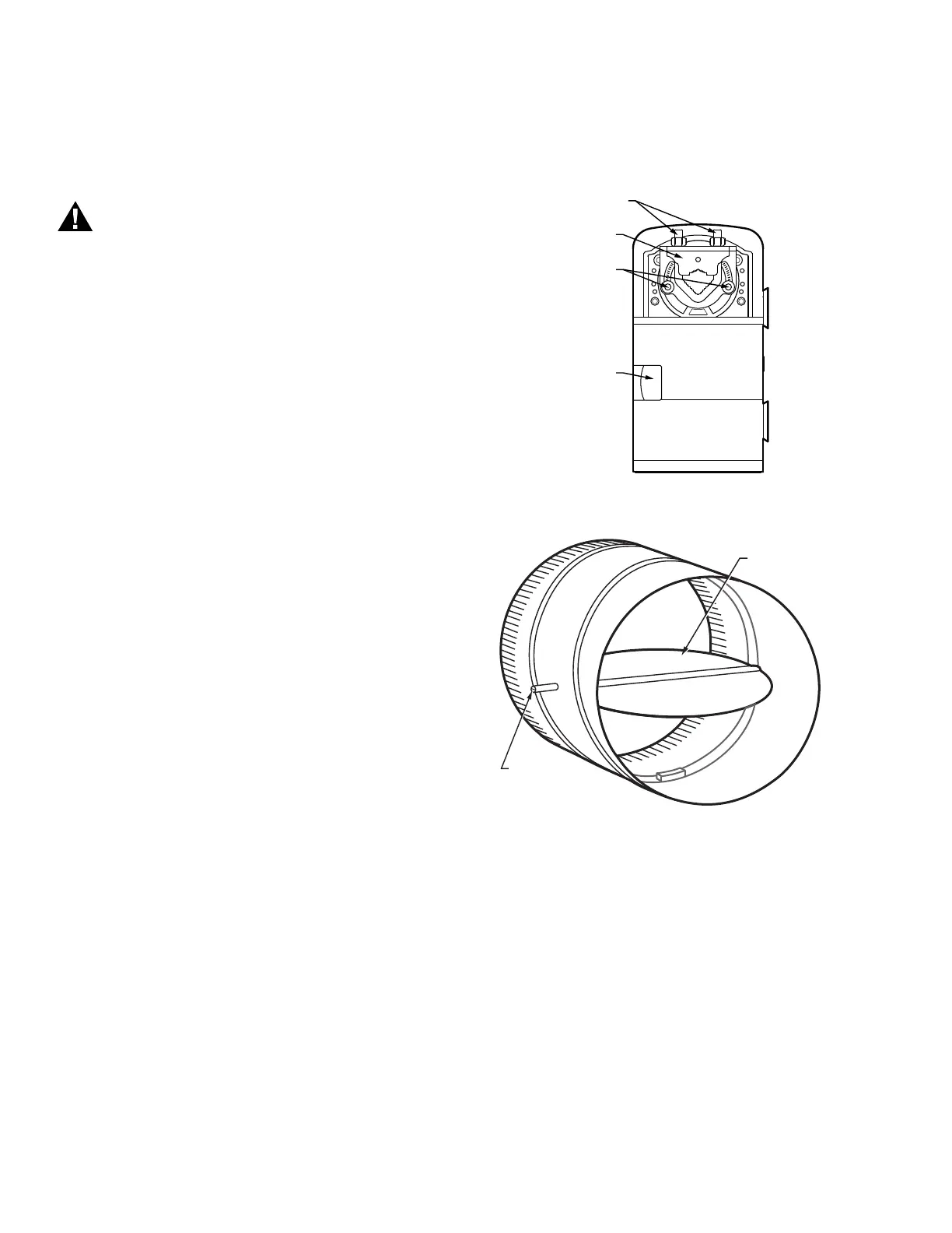
Fig. 1. Series 60 Floating Actuator.
Fig. 2. Damper with 90 degree CW rotation to open.
IMPORTANT
Mount actuator flush with damper housing or add a
spacer between the actuator mounting surface and
damper box housing.
Before Mounting Actuator onto Damper
Shaft (PVL0000AS, PVL4022AS, and
PVL6436AS)
Tools required:
— Phillips #2 screwdriver - end-limit set screw adjustment
— 8 mm wrench - centering clamp
UNIVERSAL SHAFT
CLAMPING BOLTS (2)
M23568
UNIVERSAL
SHAFT ADAPTER
MECHANICAL
END LIMIT SET
SCREWS (2)
DECLUTCH
BUTTON
M23569
DAMPER SHAFT
ROTATES
CLOCKWISE
TO OPEN
DAMPER
 Loading...