EasyManua.ls Logo

Honeywell Spyder PUL6438S User Manual

Honeywell Spyder PUL6438S
24 pages
To Next Page IconTo Next Page
Page #1 background imageLoading...
Page #1 background image
PRODUCT DATA
63-2685-03
Spyder® Lon
Programmable, VAV/Unitary Controllers
PRODUCT DESCRIPTION
The PUL1012S, PUL4024S, PUL6438S, PVL0000AS,
PVL4022AS, PVL4024NS, PVL6436AS, and PVL6438NS
controllers are part of the Spyder family. The eight controllers
are Free Topology Transceiver (FTT) L
ONMARK
®
-compliant
devices designed to control HVAC equipment. These
controllers provide many options and advanced system
features that allow state-of-the-art commercial building
control. Each controller is programmable and configurable
through software.
The Spyder Lon controllers require the Spyder Programmable
Feature to be licensed in the WEBpro workbench tool and the
WEBS AX JACE Controller for programming and
downloading. The eight Spyder Lon Models are also available
as Individually Licensed Controllers (ILC). The ILC versions
are identical in design and capability in every detail except for
the licensing. The Individual Licensing of the Spyder ILCs
(The License is built in) allows them to be programmed and
downloaded with any brand of the Niagara Workbench or
JACE controller. The Spyder ILCs are identified with a suffix
on the Part Number of -ILC. Example: PUL6438S-ILC follows
all the same Installation Instructions information as the
PUL6438S.
These controllers are for use in VAV (Variable Air Volume) and
Unitary HVAC control applications. Each controller contains a
host micro controller to run the main HVAC application and a
second micro controller for L
ONWORKS® network
communications. Each controller has flexible, universal inputs
for external sensors, digital inputs, and a combination of
analog and digital Triac outputs. The eight models are
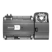
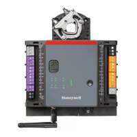
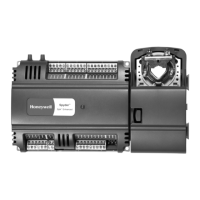
described in Table 1. The photo to the left is of the model
PVL6436AS, which includes the actuator.
Contents
Product Description .......................................................... 1
Specifications ................................................................... 3
Installation ........................................................................ 4
Checkout .......................................................................... 21
Controller Replacement .................................................... 22

Other manuals for Honeywell Spyder PUL6438S

Question and Answer IconNeed help?

Do you have a question about the Honeywell Spyder PUL6438S and is the answer not in the manual?

Honeywell Spyder PUL6438S Specifications

General IconGeneral
BrandHoneywell
ModelSpyder PUL6438S
CategoryController
LanguageEnglish

Summary

Product Overview

Ordering Information

Controller Specifications

General & Environmental Ratings

Covers rated voltage, power consumption, ambient operating conditions.

Input and Output Circuit Details

Specifications for Digital Inputs, Triac Outputs, Analog Outputs, and Universal Inputs.

Pre-Installation Review Guidance

Advises reviewing power, input, and output specifications before installation.

Installation Procedures

Actuator Mounting Steps

Instructions for mounting the actuator onto the damper shaft.

Controller Mounting Methods

Procedures for mounting the controller unit (panel/DIN rail).

Air Flow Pickup Connection

Guidance on connecting air flow pickup tubes to controller ports.

Power and Wiring

Power Budget Calculation

Process for calculating power requirements for transformer sizing.

Power Wiring Guidelines

Recommendations for safe and compliant power connections.

Line-Loss Considerations

Explains voltage drop in wiring and its effect on controller operation.

Communications Setup

LONWORKS Bus Wiring

Rules, cable types, and topology for LONWORKS® Bus networks.

Terminal Block Wiring

Procedures for attaching wires to controller terminal blocks.

Neuron Service Pin and Bus Jack

Functionality of the Neuron Service Pin and LONWORKS Bus Jack.

System Startup

Broadcasting Service Message

Process to send Service Message for device identification.

Controller Status LED

Understanding the LED states for controller operation.

Checkout and Replacement

Installation Checkout

Final verification of wiring and connections.

Controller Replacement Procedures

Steps for replacing controller assemblies or individual units.
Related product manuals