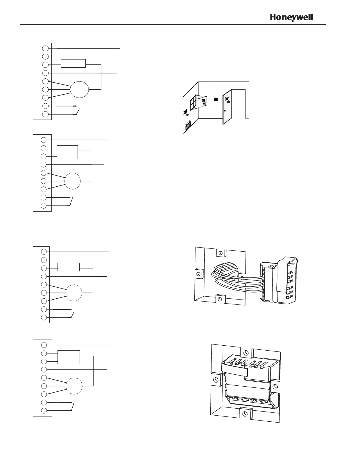
Application 3: 2 pipes 1 stage Heat or 1 stage Cool
MCO wiring diagram
Application 2: 2 pipes Cool only wiring diagram
1 Pull wires through wire hole.
Loosen screw terminals, insert wires into terminal
block, then retighten screws.
2 Push the Power box into the junction box.
APH07CH04
-
R2001EN
Install the thermostat about 5 feet (1.5m) above the
oor in an area with good air circulation at average
temperature.
Do not install in locations where the thermostat can
be affected by:
• Drafts or dead spots behind doors and in corners
• Hot or cold air from ducts
• Sunlight or radiant heat from appliances
• Concealed pipes or chimneys
• Unheated/uncooled areas such as an outside wall
behind the thermostat
Installation & Commissioning
Fig.2.3 Typical wiring for ON/OFF control in 2 pipe cooling only (VC4013)
Fig.2.4 Typical wiring for 3-wire control in 2 pipe cooling only (VC6013)
Fig.2.5 Typical wiring for ON/OFF control in 2 pipes 1H1C (VC4013)
Fig.2.6Typical wiring for 3-wire control in 2 pipes 1H1C (VC6013)
1
2
3
4
5
6
7
8
9
L
Cool valve
Fan
Remote Setback
L
1
2
3
4
5
6
7
8
9
Cool valve
Fan
Remote Setback
1
2
3
4
5
6
7
8
9
N
L
Cool valve
Fan
Remote Setback
N
L
1
2
3
4
5
6
7
8
9
Fan
valve
Remote Setback

 Loading...