T7200D,E, T7300D,E,F AND Q7300 SERIES 2000 PROGRAMMABLE COMMERCIAL THERMOSTATS AND SUBBASES
63-4355—2 8
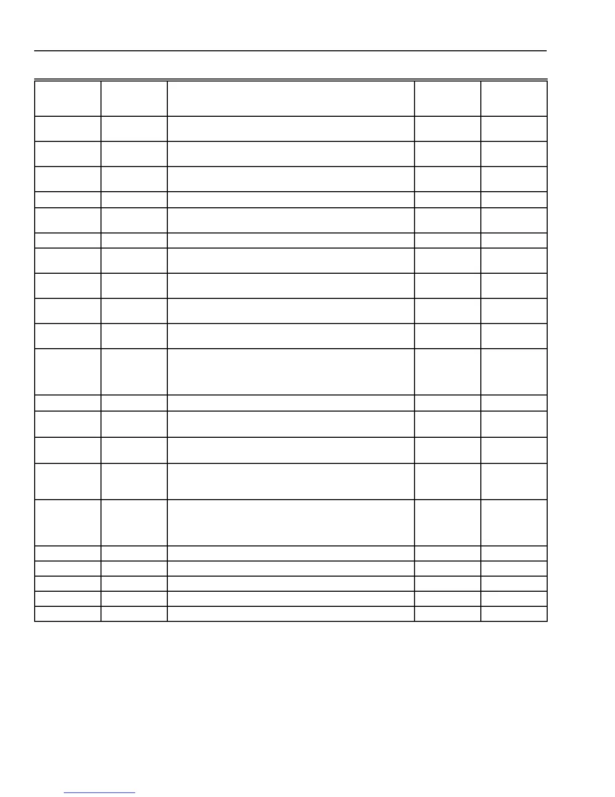
Table 6. Terminal Designations (continued).
1. Loosen the terminal screws on the subbase or wallplate
and connect the system wires. See Fig. 9.
IMPORTANT
Use 18-gauge, solid-conductor color-coded
thermostat cable for proper wiring. If using
18- gauge stranded wire, no more than ten wires
can be used. Do not use larger than 18-gauge wire.
2. Securely tighten each terminal screw.
3. Push excess wire back into the hole.
4. Plug the hole with nonflammable insulation to prevent
drafts from affecting the thermostat.
a
Some OEM models reverse the economizer terminal designations A1 and A2.
b
Some OEM models label the terminal for transformer common B.
c
Only applies to Q7300H2037 model.
Standard
Terminal
Designations
Alternate
Terminal
Designations Typical Connection Function
Terminal
Type
W1 H1, R3 Stage 1 heating relay (Q7300A, G, H) or auxiliary heat
relay (Q7300C, D, H).
Output 24V powered
contact
W2 H2, R4, W3, Y Stage 2 heating relay. Output 24V powered
contact
W3 — Stage 3 heating relay. Output 24V powered
contact
X
B
b
, C, X1, X2
Common. Input
X1, X3 A, A1, A2, C,
L, X, Z
User defined Light Emiting Diodes (LEDs). Annunciation —
X4 — LED common. Annunciation —
Y1 C1, M, Y Stage 1 compressor contactor (Q7300C, D, H). Output 24V powered
contact
Y1, Y RS, M
Stage 1 cooling compressor (Q7300A, G, H
c
, L).
Output 24V powered
contact
Y2 C2 Stage 2 cooling compressor (conventional).
Stage 2 compressor contactor (heat pump).
Output 24V powered
contact
Y3 — Stage 3 cooling compressor. Output 24V powered
contact
BM —
ML7984 Actuator connection (Q7300H
c
, L only); no call
for heat, valve closed; call for stage 1 heat, valve
approximately one-half open; call for stage 2 heat, valve
fully open.
Output —
FC —
Fan control transformer (Q7300H
c
, L only).
Input —
GH —
High-speed fan output (Q7300H
c
, L only); activate during
calls for cooling.
Output 24V powered
contact
GL —
Low-speed fan output (Q7300H
c
, L only); activated on
calls for heat and fan On selection.
Output 24V powered
contact
P1, P2 —
Pump interlock relay (Q7300H
c
, L only); operates
circulator pump in hydronic heat or energizes
conventional heat system.
Input, Output 24V powered
contact
RM —
ML7984A Actuator connection (Q7300H
c
, L only); no call
for heat, valve closed; call for stage 1 heat, valve
approximately one-half open; call for stage 2 heat, valve
fully open.
Output —
— C, H, L HSII Control Panel. — —
— O Momentary circuit changeover. — —
— P Defrost. — —
— R1, R2 Low- and high-speed fan relays. — —
— T External temperature readout, T-relay; outdoor thermistor. — —
 Loading...