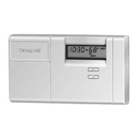
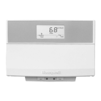
T7512A,B PROGRAMMABLE LOAD MANAGEMENT THERMOSTAT
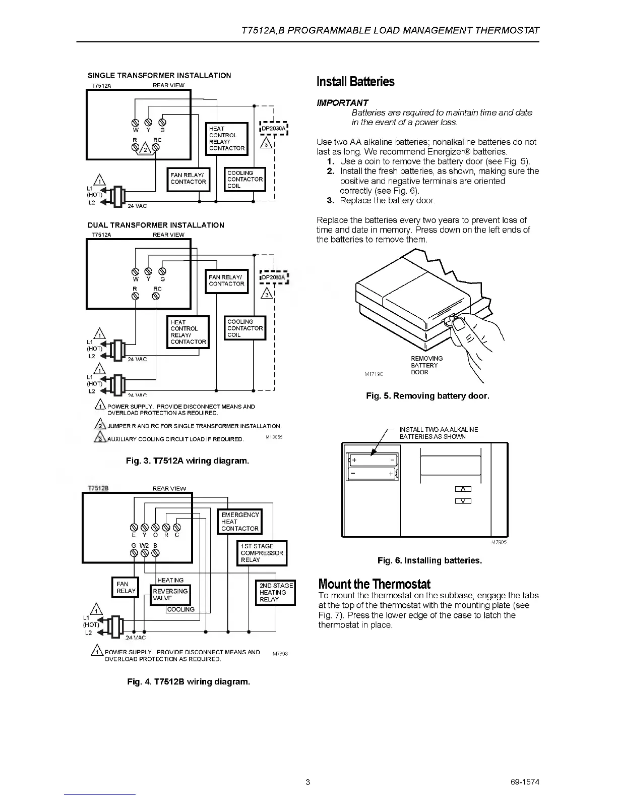
SIN G L E T R A N S F O R M E R IN STALLATIO N
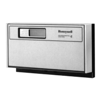
T7512A REAR VIEW
Install Batteries
IMPORTANT
Batteries are required to maintain time and date
in the event of a power loss.
Use two AA alkaline batteries; nonalkaline batteries do not
last as long. We recommend Energizer® batteries.
1. Use a coin to remove the battery door (see Fig. 5).
2. Install the fresh batteries, as shown, making sure the
positive and negative terminals are oriented
correctly (see Fig. 6).
3. Replace the battery door.
D U A L T R A N S FO R M E R INSTALLATIO N
T7512A REAR VIEW
A i
Ä
3 .
JUMPER R AND RC FOR SINGLE TRANSFORMER INSTALLATION.
AUXILIARY COOLING CIRCUIT LOAD IF REQUIRED. M13055
POWER SUPPLY. PROVIDE DISCONNECT MEANS AND
OVERLOAD PROTECTION AS REQUIRED.
Fig. 3. T7512A wiring diagram.
A
1 POWER SUPPLY. PROVIDE DISCONNECT MEANS AND M7898
OVERLOAD PROTECTION AS REQUIRED.
REAR VIEW
Replace the batteries every two years to prevent loss of
time and date in memory. Press down on the left ends of
the batteries to remove them.
M7905
Fig. 6. Installing batteries.
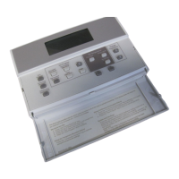
Mount the Thermostat
To mount the thermostat on the subbase, engage the tabs
at the top of the thermostat with the mounting plate (see
Fig. 7). Press the lower edge of the case to latch the
thermostat in place.
Fig. 4. T7512B wiring diagram.
3
69-1574
 Loading...