Do you have a question about the Honeywell T874R and is the answer not in the manual?
| Compatibility | Electric Baseboard, Convector, and Fan-forced Heaters |
|---|---|
| Mounting | Wall Mounted |
| Switching Action | SPST |
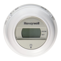
| Display | Digital |
| Voltage Rating | 24V AC |
Explains thermostat operation, stages of heat/cool, and LED indicator functions.
Details critical safety warnings for electrical shock, equipment damage, and proper handling.
Provides advice on selecting an optimal installation location for accurate temperature sensing.
Instructions for mounting the subbase on outlet boxes or walls, including leveling.
Essential installer checks before starting, including reading instructions and verifying qualifications.
Step-by-step guide for mounting the subbase on various surfaces like outlet boxes or walls.
Comprehensive instructions for connecting system wires to the subbase terminals.
Internal schematic and wiring for model Y594R1763, including system component connections.
Internal schematic and wiring for model Y594R1243, detailing heat pump system connections.
Internal schematic and wiring for model Y594R1300, featuring fixed anticipation.
Internal schematic and wiring for model Y594R1425, for universal heat/cool systems.
Wiring diagrams for Y594R1664 and Y594R1706, replacements for specific York models.
Internal schematic and wiring for Y594R1615, for systems with un-jumped W2/E terminals.
Wiring diagrams for Y594R1672 and Y594R1698, exact replacements for York models.
Internal schematic and wiring diagram for Y594R1797.
Step-by-step instructions for attaching the thermostat to the subbase, including cover removal.
Procedure for setting the adjustable heat anticipator for 2-stage heating systems.
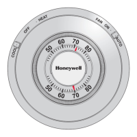
How to adjust the setpoint lever for desired heating and cooling temperatures.
Guide to using the system and fan switches on the subbase for controlling operation modes.
Steps to verify proper operation of heating, cooling, emergency heat, and fan.
Information that thermostats are factory calibrated and no field calibration is provided.
Instructions for adjusting the thermostat's internal thermometer if it deviates from accurate readings.