TC500A-N/TC500A-W COMMERCIAL THERMOSTAT
5 31-00399M-02 | Rev.03-21
Wiring the wallplate
IMPORTANT
All wiring must comply with local electrical codes
and ordinances.
NOTE: Supports 18-22 AWG (0.5-0.75mm
2
). Solid wire is
recommended.
Follow equipment manufacturer wiring instructions when
available. A letter code is located near each terminal for
identification.
CAUTION
Power must not be connected while wiring.
Wiring a unit that is powered may result in electrical
shock and/or equipment damage.
1. Connect wires to the terminals. See Fig. 6 for terminal
assignments and Table 1 for terminal descriptions.
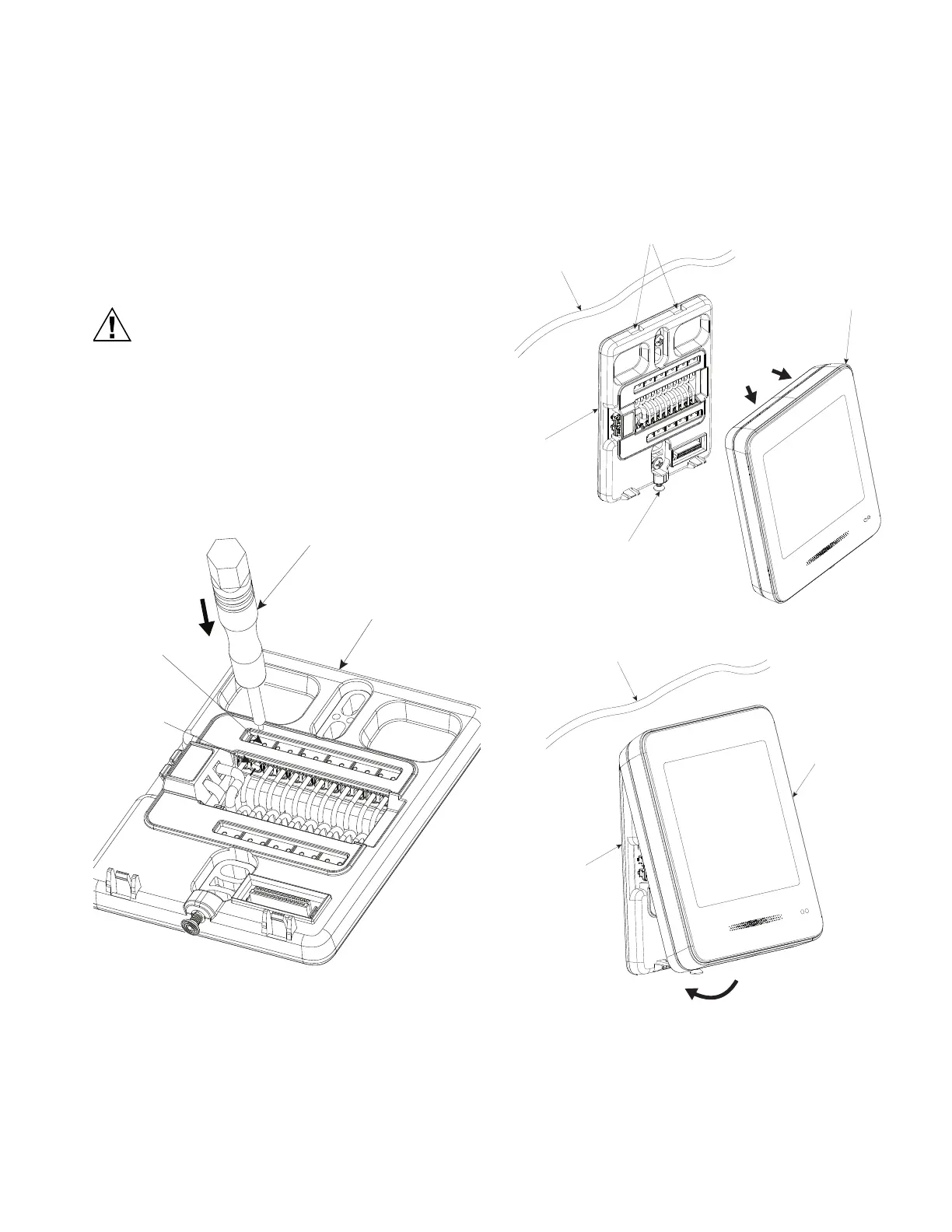
2. Insert the solid wire into the terminal hole directly.
3. (optional) To insert stranded wire end into the wiring
terminal, push the Release tool into the Tool hole and
insert the wires.
Fig. 7. Wire release
4. Push excess wire back into the hole.
5. Check for the loose or frayed wire that may cause a
short.
Mounting the display unit
After all wiring is completed, install the display onto the
wallplate.
1. Hold the display in a tilted position so the latches fit
onto the rectangular slots of the wall plate as shown
in the below image.
2. Insert the latches onto the wallplate rectangular slots
and rotate the display and push it onto wallplate.
3. Gently tighten the Security screw using a screwdriver
by turning it in the clockwise direction (screw torque
0.1Nm).
Release tool
Tool hole
Wiring
terminal
Wallplate
Wall
Wallplate
Bottom screw
Display
Rectangular slots
Latches
 Loading...