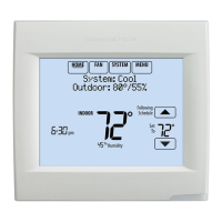
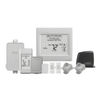
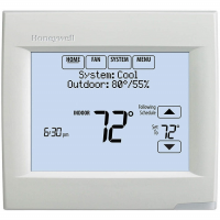
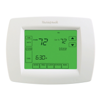
VISIONPRO
®
8000 WITH REDLINK™
11 68-0312—01
2. For 24VAC primary power, connect common side of
transformer to C terminal.
Fig. 17. Connecting C wire to terminal block.
Wiring the Thermostat
IF THE THERMOSTAT IS WIRED DIRECTLY TO THE
EQUIPMENT
1. Refer to Fig. 18. See Table 10 on page <$elempagenum
for terminal designations and “Wiring” beginning on
page 116 for more information.
2. Turn on 24VAC NOW.
NOTE: 24VAC (C wire) is required to connect RedLINK
accessories.
Fig. 18. Thermostat wired directly to equipment.
IF THE THERMOSTAT IS USED WITH AN EQUIPMENT
INTERFACE MODULE OR TRUEZONE WIRELESS
ADAPTER
1. Power the thermostat using Rc and C terminals or with
batteries. Refer to Fig. 19.
NOTE: The relay outputs and inputs on the thermostat
do not function when used with an Equipment
Interface Module or TrueZONE Wireless
Adapter.
Fig. 19. Inserting wires in thermostat terminal block.
Remove Coin Cell Battery Tab
1. Remove tab to activate coin cell battery.
NOTE: Coin cell battery saves time and date during a
power loss.
Fig. 20. Remove coin cell battery tab.
Mounting Thermostat on Wallplate
1. Align thermostat at bottom and snap into place as
shown.
Fig. 21. Mount thermostat.
S1
S1
W
Y
G
W2
Y2
A
S1
S1
O/B
Y
G
AUX
-E
Y2
L/A
K
RC
R
U1
U1
U2
U2
C
CONVENTIONAL
HEAT PUMP
S1
S1
W
Y
G
W2
Y2
A
S1
S1
O/B
Y
G
AUX
-E
Y2
L/A
K
RC
R
U1
U1
U2
U2
C
CONVENTIONAL
HEAT PUMP
S1
S1
W
Y
G
W2
Y2
A
S1
S1
O/B
Y
G
AUX
-E
Y2
L/A
K
RC
R
U1
U1
U2
U2
C
CONVENTIONAL
HEAT PUMP
REMOVE DURING
INSTALLATION

 Loading...
