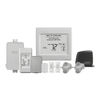
VISIONPRO
®
8000 WITH REDLINK™
68-0312—01 118
Fig. 311. Inserting wires in thermostat terminal block.
Fig. 312. Inserting wires in EIM terminal block
IMPORTANT
Use 18–22 gauge thermostat wire.
Table 11. Wiring Diagrams by System Type.
System Type
Wiring Diagram
Reference
Standard Heat/Cool 313
Heat Pump with Auxiliary Heat 314
Geothermal radiant heat 315
Heat pump with oil forced air backup. 319
Geothermal radiant heat with geothermal
forced air and backup heat using separate
transformer for the radiant heat
320
Wood stove-fired hot water fan coil with
forced air furnace backup heat
321
Hot water radiant heat with backup heat
(single zone application)
322
Hot water radiant heat with backup forced
air heat. Zoned with forced air zone panel
and zone valves
323
Hot water radiant heat with backup forced
air heat. Zoned with forced air zone panel
and hot water panel.
324
Hot water fan coil with forced air furnace
backup heat.
325
Wood stove with heat pump and backup
electric strips. (For applications in which
the thermostat only needs to run the
blower fan when stove is hot).
Wiring IAQ Equipment or a stage of
Heating/Cooling to U1, U2 or U3 terminals
326–336
Wired Remote Sensors 341–345
Table 12. Zoning Diagrams by System Type.
System Type
Wiring Diagram
Reference
RedLINK VisionPRO thermostats with an
HZ432 zone panel and no IAQ control
346
RedLINK VisionPRO thermostat
controlling one zone with an HZ432 zone
panel and a TrueSTEAM humidifier
347
RedLINK VisionPRO thermostat with an
HZ432 zone panel and a ventilator
348
RedLINK VisionPRO thermostat with an
HZ432 zone panel and a TrueDRY
dehumidifier
349
S1
S1
W
Y
G
W2
Y2
A
S1
S1
O/B
Y
G
AUX
-E
Y2
L/A
K
RC
R
U1
U1
U2
U2
C
CONVENTIONAL
HEAT PUMP
R
C
Y
Y2
G
W
O/B
W2
AUX1
W3
AUX2
A
L/A
 Loading...