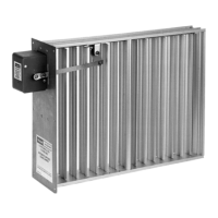
AUTOMATIC OPPOSED BLADE DAMPERS (AOBD)
11 68-0246
SERVICE
Checking Damper Blades
Occasionall
damper blades stick while openin
or closin
.
The problem ma
be caused b
a worn motor switch or
bindin
damper blades. To locate the problem:
1.
Remove the electric actuator enclosure, if necessar
.
2.
Separate the crank arm from the motor shaft usin
a 1-
16 Allen wrench.
3.
Usin
our hand, open and close the damper blades
several times b
pushin
and pullin
the crank shaft:
a. If linka
e and damper blades move freel
, the
are
workin
correctl
.
b. If linka
e and damper blades re
uire effort to open
or close, replace the damper and repeat step 2.
4.
If the damper blades still re
uire considerable effort to
open or close, check that the damper is sized correctl
and that there is no pressure on the damper blades. If
the damper is not sized correctl
, replace the old
damper with a correctl
-sized damper.
5.
Attach the crank arm to the motor drive shaft.
6.
If the damper blades continue to stick while openin
or
closin
, refer to the Installation Instruction to ensure the
mountin
screws are installed correctl
.
7.
Be sure the damper blades close full
b
shortin
termi-
nals 5 and 6. If there is a
ap between damper blades:
a. Loosen the crank arm from the motor drive shaft
usin
a 1-16 Allen wrench.
b. Manuall
close the
ap between the damper blades.
c. Ti
hten the crank arm to the motor drive shaft usin
a 1-16 Allen wrench.
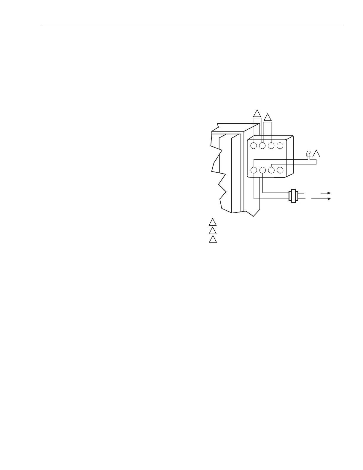
Checking Electric Actuator (See Fig. 16)
1.
Remove wires from the damper terminals.
2.
Connect 24 Vac to electric actuator terminals 1 and 2.
3.
Ensure the electric actuator operates correctl
:
a. Remove wires from terminals 4 and 6.
b. Short terminals 4 and 5 to open the damper blades.
c. Short terminals 5 and 6 to close the damper blades.
1
If the dampers open and close as indicated, the
s
stem is operational.
2
If the dampers do not operate, as indicated,
replace the electric actuator and repeat steps 1
and 2.
4.
Ensure the end-switch operates correctl
:
a. Connect a 24 Vac test li
ht between terminals 1 and
3.
b. Short terminals 4 and 5:
1
When the damper blades are full
open, the
end-switch en
a
es, the 24 Vac test li
ht turns
on, and the electric actuator turns off.
c. Short terminals 5 and 6:
1
When the damper blades are full
closed, the
end-switch en
a
es, the 24 Vac li
ht turns off,
and the electric actuator turns off.
5.
If the motor and end-switches do not operate, as indi-
cated, replace the electric actuator and repeat steps 1
throu
h 4.
6.
Replace the electric actuator enclosure.
Fig. 16. Checking the electric actuator.
Replacing Electric Actuator
IMPORTANT
Electric actuator is shipped in the open damper posi-
tion.
1.
Usin
a 1-16 Allen wrench, loosen the crank arm set-
screw that connects the crank arm to the motor drive
shaft.
2.
Remove the crank arm from the motor drive shaft.
3.
Remove the two screws from the crank arm side of the
actuator box.
4.
Remove the electric actuator from the actuator box.
5.
Install the new electric actuator into the actuator box.
6.
Ti
hten the two screws into the crank arm side of the
actuator box.
7.
Attach the crank arm to the motor drive shaft.
8.
Ti
hten the crank arm set screw.
4
56
z
1
2
3
x
L1 (HOT)
L2
24V
24V
TEST
LIGHT
SHORT TERMINALS 4 AND 5 TO OPEN DAMPER BLADES.
SHORT TERMINALS 5 AND 6 TO CLOSE DAMPER BLADES.
24V TEST LIGHT TURNS ON WHEN DAMPER BLADES OPEN
AND TURNS OFF WHEN DAMPER BLADES CLOSE.
M2278A
1
2
3
1
2
3
 Loading...