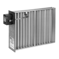
AUTOMATIC OPPOSED BLADE DAMPERS (AOBD)
68-0246 8
WIRING
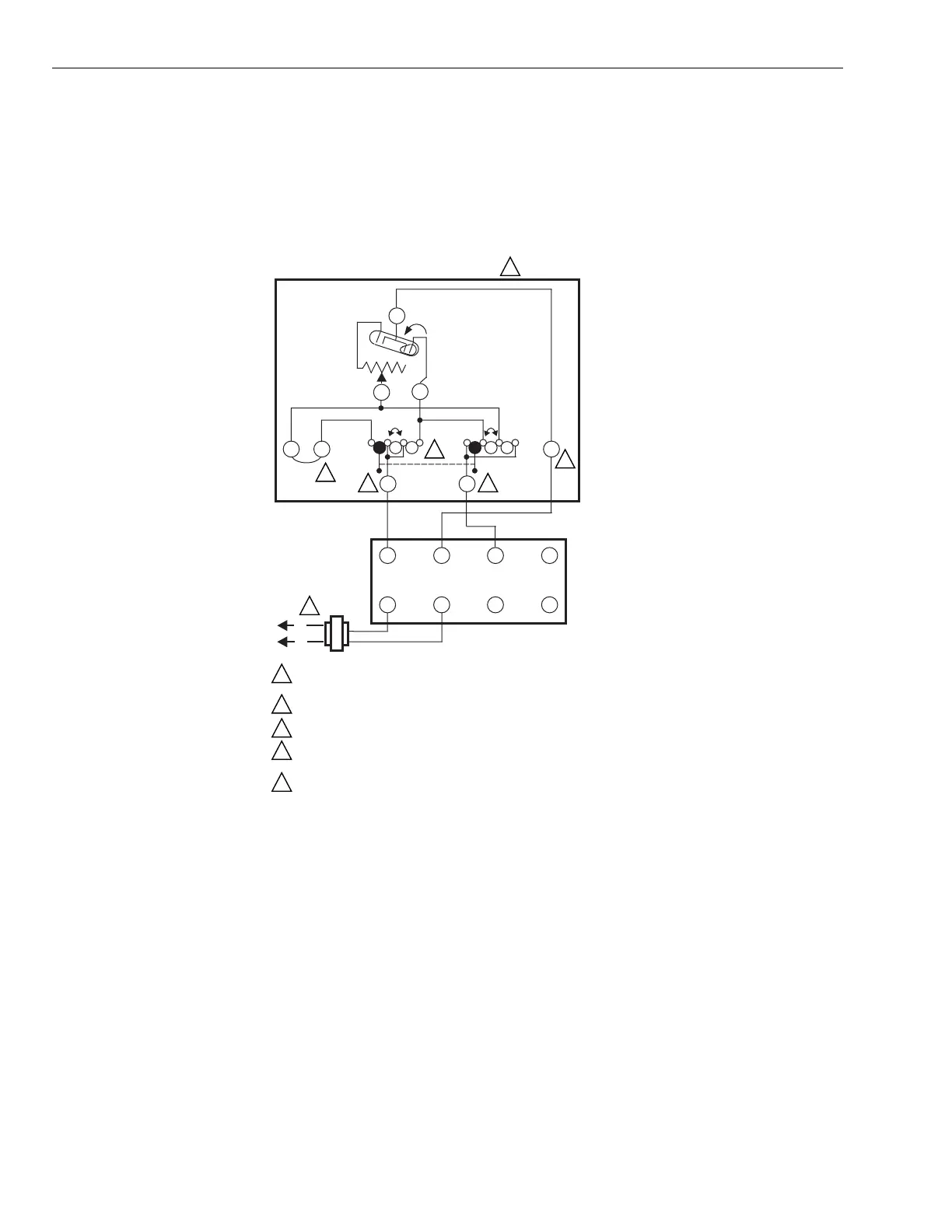
Wiring Independent Zone Applications, See
Fig. 11
For independent zone applications, follow the thermostat
wirin
instructions, if available, or see Fi
. 11 for a t
pical
wirin
dia
ram.
Fig. 11. Independent zone application wiring diagram.
Wiring Zone Systems
For zone s
stems, follow the thermostat and central lo
ic
panel wirin
instructions, if available.
Wiring Tandem Dampers (See Fig. 12-14)
When two dampers are controlled b
the same thermostat
or
older panel with five-wire control circuit
, such as occurs when
two re
isters, diffusers, or dampers suppl
the same room or
zone, the second unit is controlled b
the switch action of the
first unit
see Fi
. 12
.
A tandem wirin
dia
ram for use with an electric panel is
shown shown in Fi
. 13.
6
J
J
COOL
HEAT
HEAT
COOL
W1
Y1
ADJUST-
ABLE
HEAT
ANTICIPATOR
T87F/Q539B INTERNAL SCHEMATIC
R1
TEMPERATURE
FALL
T87F
4
5
4
5 6 Z
1 2 3
X
DAMPER
ACTUATOR
L2
L1
POWER SUPPLY. PROVIDE DISCONNECT MEANS AND OVERLOAD
PROTECTION AS REQUIRED.
TERMINALS DUAL MARKED — R/5, W/4, Y/6 — ON 137421 WALLPLATE.
NO SYSTEM SWITCHING ON 137421 WALLPLATE.
FOR CORRECT SYSTEM OPERATION, DO NOT DISCONNECT FACTORY-
INSTALLED J-J JUMPER ON Q539B.
USE T87F3715/Q539B1039 OR T87F3707/Q539B1021.
M1366C
(HOT)
(COM) (HOT)
1
1
2
2 2
2
3
3
4
4
5
5
 Loading...