AUTOMATIC OPPOSED BLADE DAMPERS (AOBD)
9 68-0246
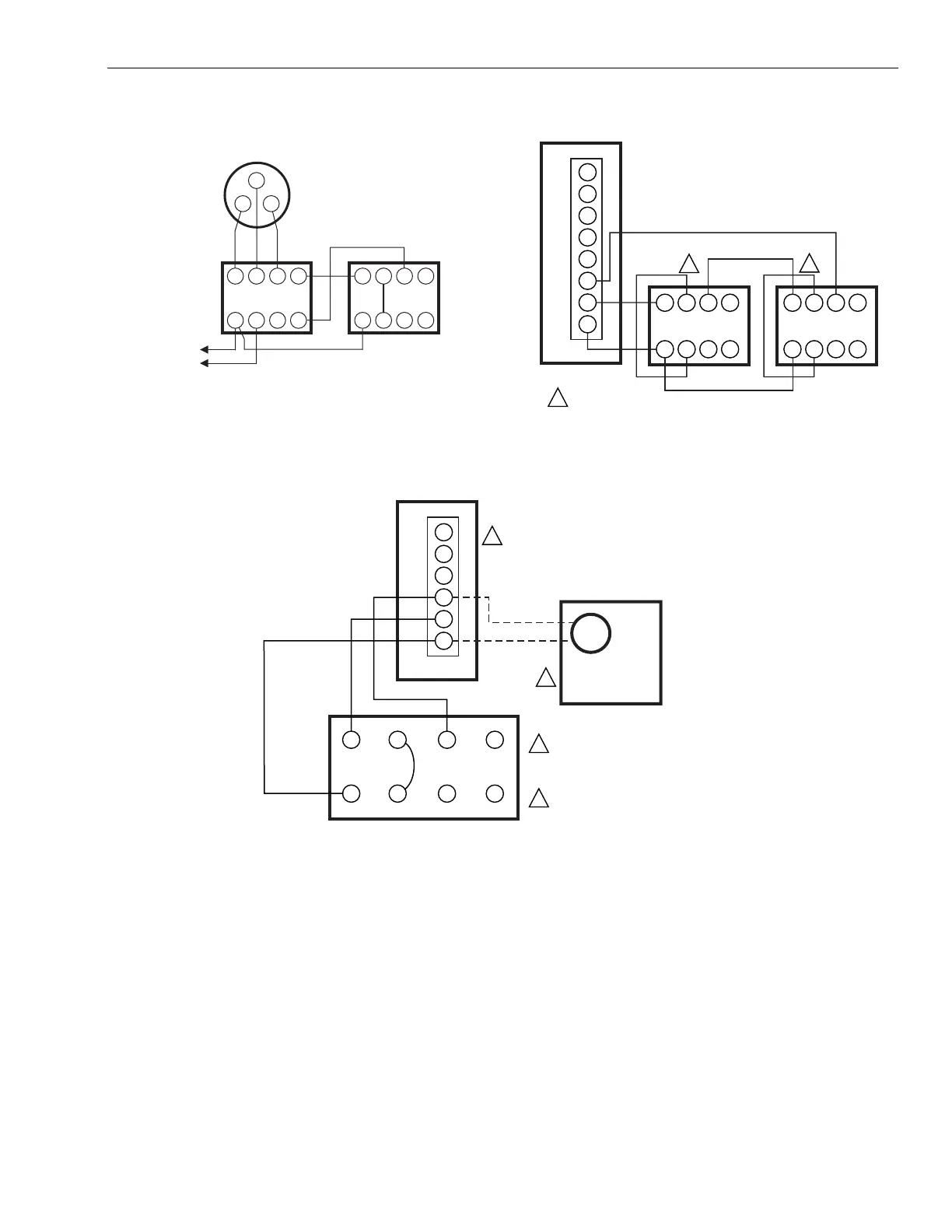
Fig. 12. Tandem wiring of dampers to the thermostat in an
independent zone application.
Fig. 13. Typical tandem wiring diagram with control panel.
Fig. 14. Tandem wiring of automatic opposed blade damper (AOBD) and automatic round damper (ARD).
4 56Z
123X
4 56Z
DAMPER
ACTUATORS
12 3X
THERMOSTAT
M885
6
5
4
TO 24V
T8
T7
T6
T5
T4
M6
M4
M1
4
5
6
Z
1
23
X
DAMPER
ACTUATOR
4
5
6
Z
1
23
X
DAMPER
ACTUATOR
TYPICAL CONTROL PANEL
1
1
1
JUMPER TERMINALS 2 AND 5 ON DAMPER ACTUATORS.
M2280D
T6
T5
T4
M6
M4
M1
TYPICAL
CONTROL PANEL
1
2
1
2
4
56Z
1
23X
OPPOSED
BLADE
DAMPER
ACTUATOR
TO ATTACH ARD TO OLDER STYLE
(5-WIRE) PANELS, CONNECT
JUMPER BETWEEN PANEL
TERMINALS M2 AND M5.
ARD OPENS LAST.
MOTOR
M14847
ARD
 Loading...