69-2072—09 10
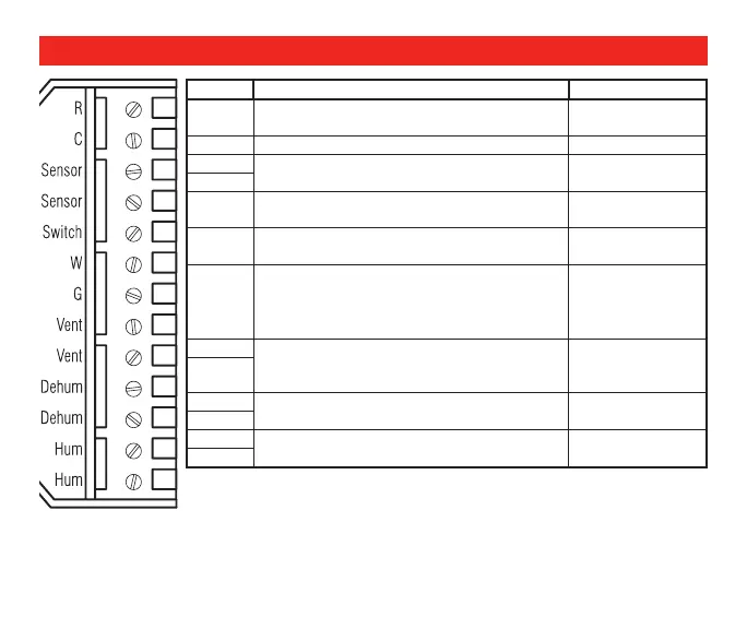
Pin Pin description Pin capacity
R 24V supply. Must be common to G output. 24Vac±20% 1.5
amp max
C 24V supply common. 24Vac±20%
Sensor Communication and supply bus to remote
sensors (sensor pins not polarized).
24Vdc 64mA max
out
Sensor
Switch Override switch input. Active when R is
applied
24Vac±20%,
10mA max in
W W input to sense when the thermostat is
calling for heat. Active when R is applied.
24Vac±20%,
10mA max in
G G input to sense fan calls. Active when R is
applied. Fan output to activate system fan.
R8222 Isolation Relay may be required if G
is not isolated through the thermostat.
24Vac±20%,
10mA max in
24Vac from R,
1Amp max out
Vent 1 Dry contact output. Opens the vent
damper of an HRV or the bathroom fan
and Damper.
24Vac from R,
1Amp max out
Vent 2
Dehum 1 Dry contact output. Starts the
Dehumidifier or an alternate fan speed.
24Vac from R,
1Amp max out
Dehum 2
Hum 1 Dry contact output. Starts the Humidifier. 24Vac from R,
1Amp max out
Hum 2
Wiring
M24819
 Loading...