9 69-2072—09
Installation
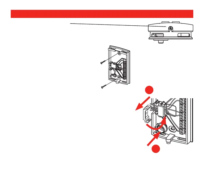
3. Loosen the cover screw.
4. Separate the front housing from the base.
M24814
5. For wall mounting, run wires through
the back hole to the terminals. Wire
size for all connectors:
2 x 18 AWG to 1 X 22 AWG.
Install the mounting plate using two
screws.
M24818
6. For duct mounting, (A) snap out side wall clip and attach
as shown. Run wires through the side wall hole, under
the clip, to the terminals. (B) Snap in sensor cap.
7. Reinstall the front housing on the power base, and
secure with screw.
Note: If duct mounted, ensure sensor cap tip aligns with
air flow in duct.
8. Apply power to the system.
M24854
A
B
 Loading...