V4055A,B,D,E ON-OFF FLUID POWER GAS VALVE ACTUATOR
60-2309—10 6
Replace V4034 Actuator on V5034 Valve
IMPORTANT
When replacing a standard (26 sec.) V4034 Actuator
on a V5034 Valve, check the main burner
flame-establishing period (MFEP) of the burner
primary safety control. If the MFEP is 10 sec.,
you must use a fast-opening (13 sec.) V4055
Actuator on the older V5034 Valve.
The initial action of the V4055 Actuator does not
immediately open the V5034 Valve because of a
difference in stroke length. The pilot may be shut
off before the main burner flame is established.
However, the fast-opening V4055 Actuator opens
the V5034 Valve quickly enough to establish the
main burner flame within the ten second flame-
establishing period.
If it is desirable to maintain the slower opening
characteristic of the standard V4034 Actuator,
both the V4034 Actuator and V5034 Valve should
be replaced with a standard V4055 Actuator on a
V5055 Valve.
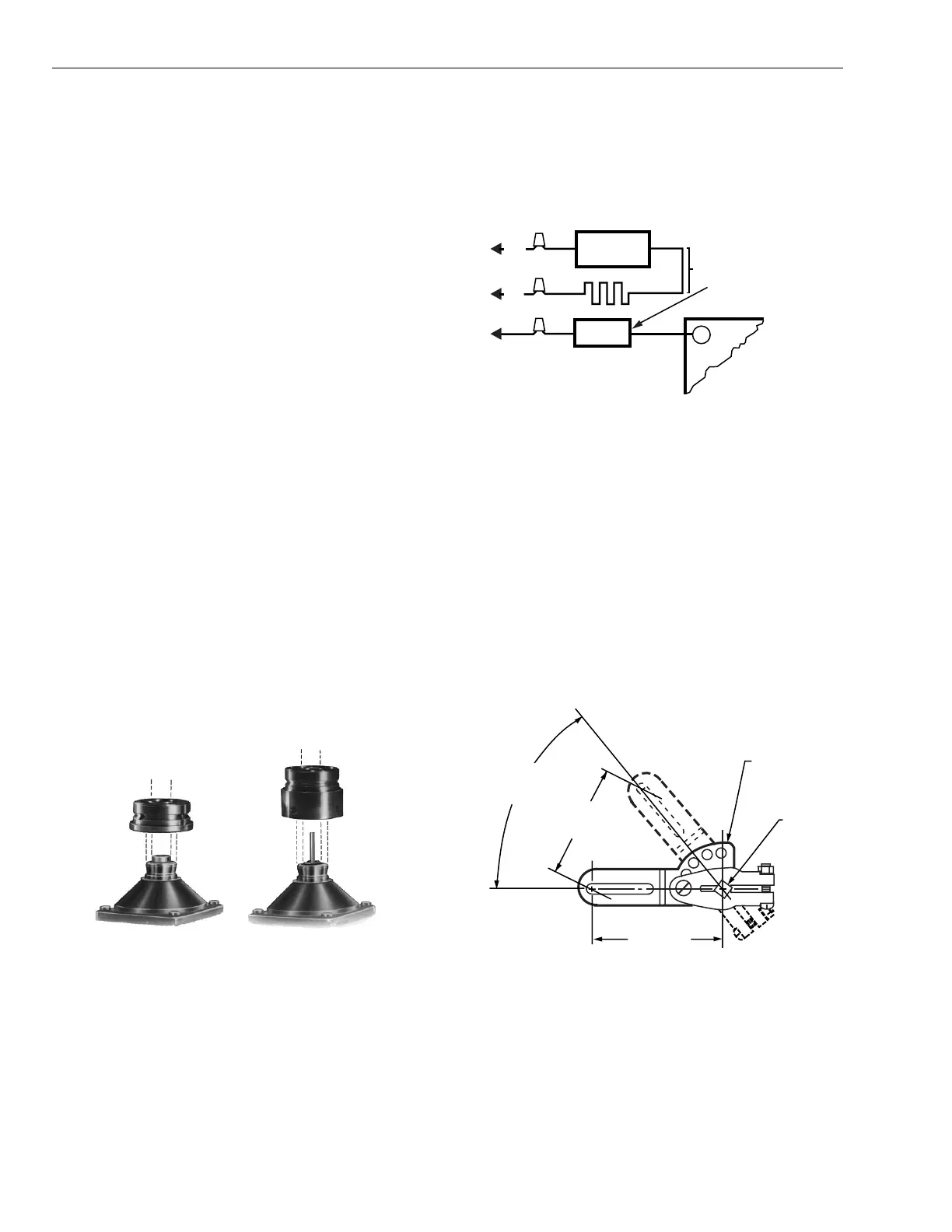
Select the correct adapter, depending on whether the V5034
Valve has a long or short stem (Fig. 3). Fasten the adapter to
the V5034 Valve bonnet, and then mount the actuator on the
adapter. Follow the instructions for mounting the actuator on
the valve.
If the V4034 being replaced is equipped with a heater, there is
a low limit control connected in series with the V4034 Actuator
power supply to prevent actuator operation below 25°F (-4°C).
There is also a constant source of line voltage power to the
heater and thermostat.
Fig. 3. Use adapters to connect V4055
Actuator with V5034 Valve.
The V4055 is rated for ambient temperatures down to -40°F
(-40°C) for 60 Hz models, or -10°F (-23°C) for 50 Hz and
50/60 Hz models, and does not require a heater. Remove all
the wiring associated with the heater. Disconnect the power
supply for the heater at its source and remove the wires.
See Fig. 4.
Fig. 4. Remove heater circuits, if installed,
when replacing V4034 Actuator.
Mount and Adjust 7616BR
Damper Crank Arm (If Used)
IMPORTANT
When a damper crank arm is used with a NEMA 4
actuator that is exposed to ice or sleet, a suitable
shield must be installed to prevent ice or sleet
buildup.
Follow installation and adjustment directions included with
damper crank arm. Maximum pushrod travel is 2-5/16 in.
(59 mm) through a stroke of 52 degrees. See Fig. 5.
Fig. 5. 7616BR Damper Crank Arm can be attached to
actuator shaft to drive a damper when valve is open.
USE NO. 133533A
ADAPTER WITH
SHORT STEM V5034
USE NO. 133534A
ADAPTER WITH
LONG STEM V5034
M732
1
HEATER
THERMOSTAT
LOW
LIMIT
HEATER
CIRCUIT
HEATER
L1
(HOT)
TO MAIN
VALVE TERMINAL
ON BURNER CONTROL
L2
BLACK
WHITE
REMOVE HEATER CIRCU
COMPLETELY AND
REMOVE LOW LIMIT
V4034
M7333
52 DEGREE
ANGULAR
ROTATION
MAXIMUM
TRAVEL
SHAF
7616BR
DAMPER
ARM
M7322
RADIUS
2-11/16 (68.3)
2-5/16 (58.7)

 Loading...