V4055A,B,D,E ON-OFF FLUID POWER GAS VALVE ACTUATOR
7 60-2309—10
WIRING
WARNING
Electrical Shock Hazard.
Can cause serious injury or death.
Disconnect power supply before making wiring
connections to prevent electrical shock and equipment
damage.
Wiring must comply with all applicable electrical codes,
ordinances and regulations. Wiring to the actuator must be
NEC Class 1.
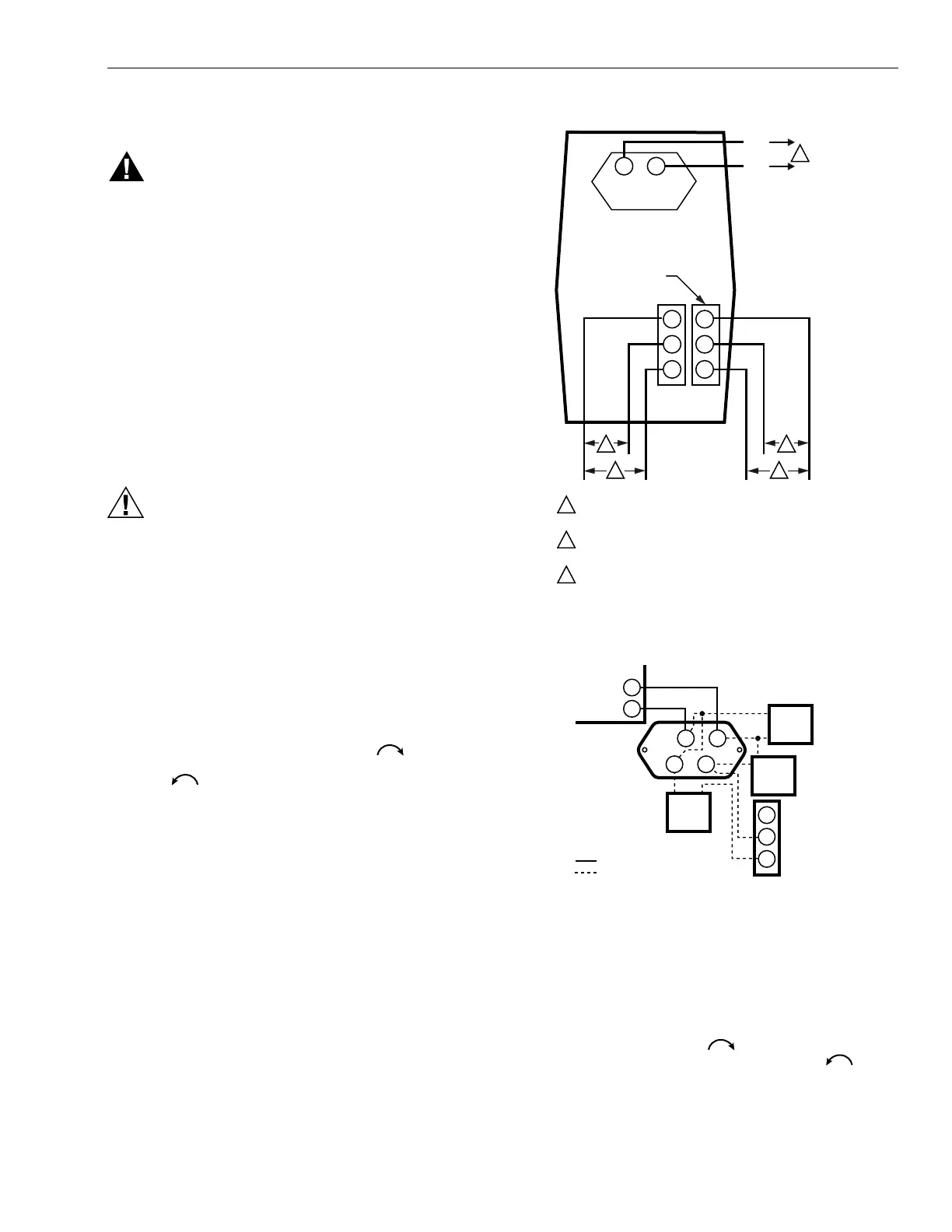
Connect the power supply to terminals 1 and 2 on the V4055
terminal strip. Refer to Fig. 6 for Auxiliary Switch connections
and Fig. 7 for Max Flow Limit Switch connections. For typical
system hookups, refer to Fig. 8 and to instructions packed
with the device used to control the valve.
When all wiring connections are complete, replace the
actuator faceplate.
CAUTION
Operation Hazard.
Improper wiring can cause improper and
dangerous operation.
Label all wires prior to disconnection when servicing
valves. Wiring errors can cause improper and
dangerous operation.
NOTE: Pipe sealant is required on the conduit threads of
actuators with NEMA 4 enclosures.
Adjust Auxiliary Switch (If Used)
The Auxiliary Switch is adjustable throughout the stroke of
the actuator. With the switch installed in the actuator, turn
the adjusting screw (see Fig. 2) clockwise to cause the
switch to operate earlier in the stroke or counter-
clockwise to cause the switch to operate later in the
stroke.
Fig. 6. External connections to the V4055 Actuator.
Fig. 7. Connecting the Max Flow
Limit Switch to the actuator.
NOTE: The Proof-of-Closure Switch is not adjustable.
Adjust Max Flow Limit Switch (If Used)
The Max Flow Limit Switch is adjustable throughout the stroke
of the actuator. With the switch installed in the actuator, turn
the adjusting screw clockwise to cause the switch to
operate earlier in the stroke or counter-clockwise to
cause the switch to operate later in the stroke.
1
2
3
2
1
1
2
AUXILIARY
SWITCH
L1
HOT
L2
POWER SUPPLY. PROVIDE OVERLOAD PROTECTION AND
DISCONNECT MEANS AS REQUIRED.
SWITCH BETWEEN THESE TWO LEADS IS CLOSED WHEN
VALVE IS SHUT (DE-ENERGIZED).
3
SWITCH BETWEEN THESE TWO LEADS IS OPEN WHEN
VALVE IS SHUT (DE-ENERGIZED).
NO
NC
C
NO
NC
C
PROOF-OF-CLOSURE
SWITCH
2
3
M1279
C
7800 SERIES
RELAY
MODULE
NC
NO
ADJUSTABL
MAX
FLOW
LIMIT
SWITCH
FIELD WIRING
INTERNAL WIRING
TRAVEL
LIMIT
SWITCH
PUMP
MOTOR
PUMP
VALVE
1
L2
9
2
34

 Loading...