60-2309—10 G.R. Rev. 2-01 www.honeywell.com/building/components
Printed in U.S.A. on recycled
paper containing at least 10%
post-consumer paper fibers.
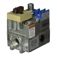
V4055A,B,D,E ON-OFF FLUID POWER GAS VALVE ACTUATOR
Home and Building Control Home and Building Control Honeywell Asia Pacific Inc. Honeywell Europe S.A. Honeywell Latin American
Honeywell Honeywell Limited-Honeywell Limitée Room 3213-3225 3 Avenue du Bourget
Region
1985 Douglas Drive North 35 Dynamic Drive Sun Hung Kai Centre 1140 Brussels 480 Sawgrass Corporate Parkway
Golden Valley, MN 55422 Scarborough, Ontario No. 30 Harbour Road Belgium Suite 200
M1V 4Z9 Wanchai Sunrise FL 33325
Hong Kong
CHECKOUT AND SERVICE
CAUTION
Equipment Damage Hazard.
Unskilled technicians can cause equipment
damage.
Only a trained, experienced, flame safeguard
technician should check out and service this control.
Checkout
After the installation is complete, cycle the valve several times
with the manual fuel shutoff cock closed before testing the
system in actual operation.
Service
The actuator is not field repairable except for replacing the
Auxiliary Switch, Max Flow Limit Switch or Proof-of-Closure
Switch. See Installation section for procedure. Do not
disassemble the valve actuator.
If the actuator fails to operate properly, replace it.
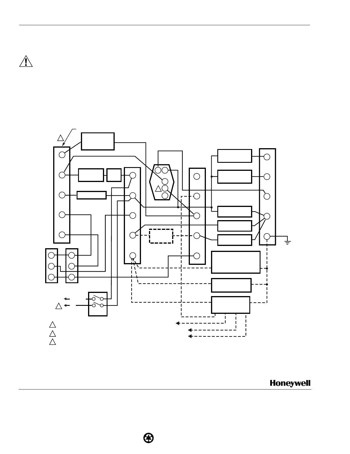
Fig. 8. Typical application of a V4055D/V5055C/V5097D or V4055E/V5055E/V5097E combination to meet Factory Mutual
or Underwriters Laboratories Inc. approved requirements for Proof-of-Closure Switch (valve seal overtravel interlock).
3
1
1
3
4
9
10
B
R
W
B
R
W
11
WIRING SUBBASE TERMINAL STRIP (4)
R414OL FLAME SAFEGAURD CONTROLS
2
LOCKOUT
INTERLOCKS
(INCL. AIRFLOW
SWITCH)
BURNER
CONTROLLER
LIMITS
ALTERNATE
LOW-FIRE
SWITCH
ALARM
HIGH-FIRE
COMMON
MODULATE
LOW-FIRE
ERIES 90
ONTROLLER
SERIES 90
FIRING RATE
MOTOR
120V, 60 HZ
POWER
SUPPLY
L1 (HOT)
L2
RECTIFYING FLAME
ROD, RECTIFYING
PHOTOCELL, OR INFRARED
(LEAD SULFIDE)
FLAME DETECTOR
10 SECOND
INTERRUPTED
PILOT/IGNITION
15 SECOND
INTERRUPTED
PILOT/IGNITION
BURNER
MOTOR
LOW-FIRE
SWITCH
HIGH-FIRE
SWITCH
C7012A, C, E,F
OR C7076A
ULTRAVIOLET
FLAME DETECTOR
C7027A, C7035A, OR
C7044A, ULTRAVIOLET
FLAME DETECTOR
POWER SUPPLY. PROVIDE DISCONNECT MEANS AND OVERLOAD
PROTECTION AS REQUIRED.
2
USE ALL NEC CLASS 1 WIRING.
3
PROOF-OF-CLOSURE SWITCH IN PREIGNITION INTERLOCK CIRCUIT;
SWITCH IS CLOSED NC-C WHEN ACTUATOR IS DE-ENERGIZED.
V4055D OR E
L1
1 2
18
17
16
15
14
C
NC
NO
L2
12
13
F
5
6
7
8
G
BLUE WHITE
YELLOW
BLUE
WHITE
WHITE
BLACK
BLACK
L2
L2
L1
OR
OR
MASTER
SWITCH
M7335

 Loading...