V4730C/V8730C/V4734C 1:1 Gas/Air Servo Regulated Gas Valves
2 EN2R-9074 0612R1-NE
SPECIFICATIONS
The specifications in this section are related to the Venturi
Mixing Unit (VMU) and Combination Gas Valve.
Models: See Table 1
a
When used with VMU335 Venturi UnitAnwendung
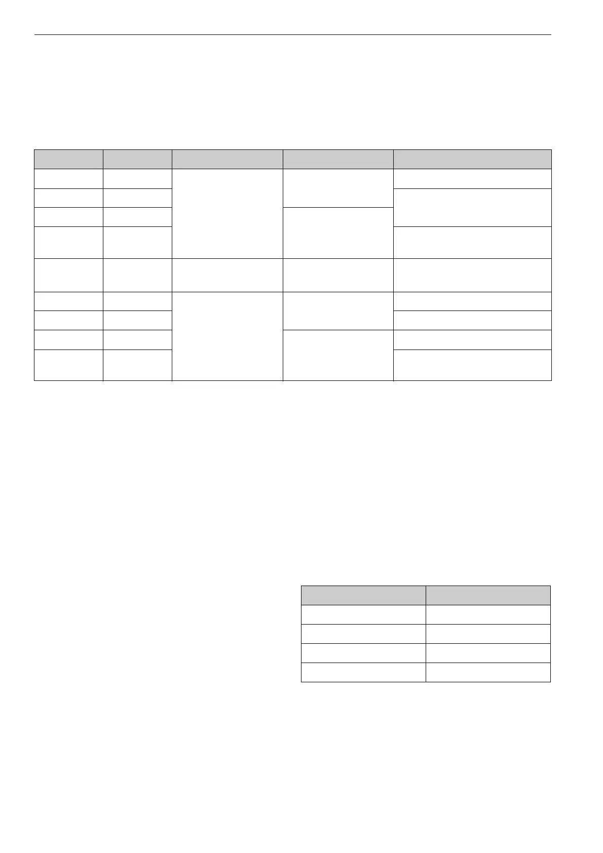
Table 1: Model Information
Model Number Size (in.) Voltage/Frequency V1 + V2 Total Current Capacity (Natural Gas 0.64sp.gr)
V4730C1006 1/2 120 Vac, 50/60 Hz 0.32 A 22-150 kW (73-512 kBtuh)
V4730C1014 3/4 43-300 kW (146-1024 kBtuh)
V4730C1022 1 0.5 A
V4730C1030 1-1/4 55-382 kW (185-1300 kBtuh)
a
/71 -
500 kW (245-1710 kBtuh)
V4734C1002 1-1/4 120 Vac, 50/60 Hz 2.6 A at start
1.04 A during operation
97-680 kW (326-2287 kButh)
when used with VMU680 unit
V8730C1007 1/2 24 Vac, 50/60 Hz 1.56 A 22-150 kW (73-512 kBtuh)
V8730C1015 3/4 43-300 kW (146-1024 kBtuh)
V8730C1023 1 1.72 A
V8730C1031 1-1/4 55-382 KW (185-1300 kBtuh)
a
/71 -
500 KW (245-1710 kBtuh)
Maximum Operating Pressure (UL):
1.45 psi (100 mBar), except for 1-1/4 in. size:
(24V): 1 psi (70 mBar).
(120V): 1.45 psi (100mBar)
CSA Approved: 0.5 psi (34 mBar).
Note: CSA Certification to 1/2 psi.
Connections:
1/8 in. (3 mm) NPT pressure taps at inlet and outlet flanges. Eight
flange connections are provided at the main body to mount either
a pressure switch (high or low) or a ValveProving System (VPS).
Torsion and Bending Stress:
Pipe connections meet EN151, Group 2, requirements.
Electrical Equipment:
Standard DIN plug connector with 36-in. (914 mm) leadwires.
Valve Position Indicator Lamps:
Inboard (closest to the valve body) - V1.
Outboard - V2.
Ambient Temperature Range:
5°F to 140°F (-15°C to +60°C).
Coil Insulation Solenoid Valves:
Class H insulation system.
Body Material:
Aluminum alloy, die-cast
Strainer:
Fine mesh screen (0.135 in. [0.34 mm] diameter). AISI 303 steel,
serviceable after removing inlet flange screws. Meets EN161 re-
quirements for strainers
Seals and Gaskets:
Hydrocarbon-resistant NBR and Viton rubber types.
Flange Kit:
Consists of one flange with sealing plug, one O-ring and four
screws. See Table 2.
Note: Valve comes with one kit only.
Manual Shut-Off Valve Kits:
50002653-001 for use with 1 in. NPT or smaller valves.
50002653-002 for use with 1-1/4 in. NPT valves.
Table 2: Flange Kits.
Part Number Size NPT in in. (mm)
32006652-001 1/2 (13)
32006652-002 3/4 (19)
32006652-003 1 (25)
32006652-004 1-1/4 (32)
 Loading...


